Palmgren Operating Manual & Parts List
84115
5
ASSEMBLY (CONTINUED)
•
Planer/molder is supplied with mounting hardware. Insert a
8-1.25 x 80mm hex head bolt with 8mm flat washer into each of
the four mounting holes on the base casting. Fasten bolts with
an 8mm flat washer and hex nut from underneath the stand top.
•
Tighten all four bolts and make sure planer/molder is securely
mounted on stand.
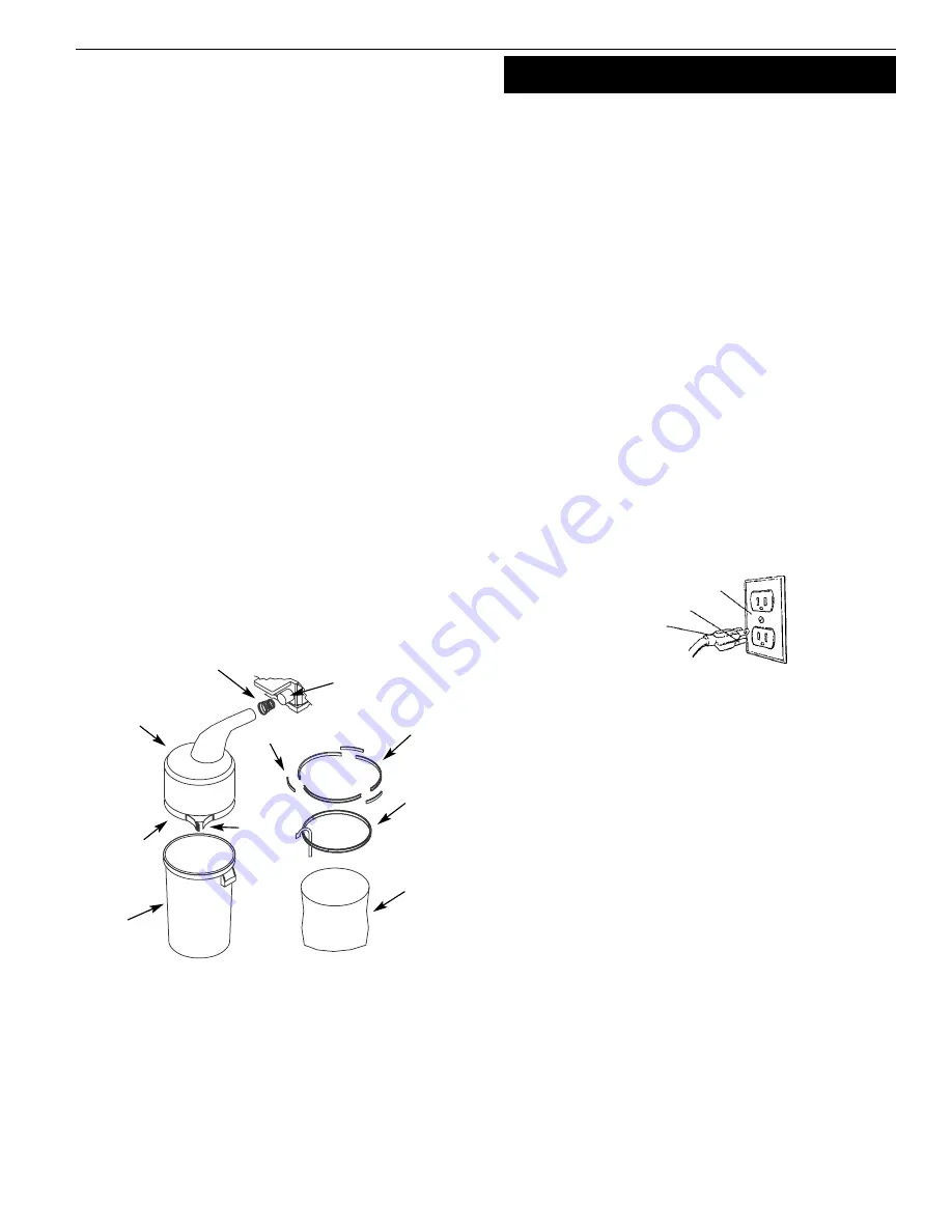
INSTALL THE HALF BAG DUST COLLECTION SET
Refer to Figure 8.
The Palmgren Half Bag Dust Collection Set is designed to provide
dust collection for woodworking tools with a 2
1
/
2
″
diameter dust
exhaust port. The filter bag attaches to a 30-gallon trash can or a
30-gallon x 1.3 mil plastic trash bag for easy, convenient sawdust
disposal (trash can and plastic trash bag not included).
•
Mount planer/molder to stand before installing Dust
Collection Set.
To use dust collection set with a trash can:
•
Place spring inside filter bag arm.
•
Slide arm with spring over dust chute.
•
Place band of the bag over rim of trash can and secure bag
by tightening strap.
To use dust collection set with a trash bag:
•
Place spring inside filter bag arm.
•
Slide arm with spring over dust chute.
•
Assemble bag support. Slide connectors into channels of
support segments.
•
Slide plastic trash bag inside and over bag support. Let bag
overlap 3-4
″
.
•
Place band of the filter bag over and into the channel of the
bag support.
•
Secure in position by tightening strap.
INSTALL RETURN ROLLERS
Refer to Figure 35, page 18.
•
Insert return rollers (Ref. No. 11) into roller bushings (Ref. Nos. 1
and 2).
IIN
NS
ST
TA
AL
LL
LA
AT
TIIO
ON
N
POWER SOURCE
WARNING:
Do not connect planer/molder to the power source
until all assembly steps have been completed.
The motor is designed for operation on the voltage and frequency
specified. Normal loads will be handled safely on voltages not
more than 10% above or below specified voltage. Running the unit
on voltages which are not within range may cause overheating
and motor burn out. Heavy loads require that voltage at motor ter-
minals be no less than the voltage specified on nameplate.
•
Power supply to the motor is controlled by a switch with key.
Removing the key from switch will lock the unit and prevent
unauthorized use.
GROUNDING INSTRUCTIONS
WARNING:
Improper connection of equipment grounding con-
ductor can result in the risk of electrical shock. Equipment must be
grounded while in use to protect operator from electrical shock.
•
Check with a qualified electrician if you do not understand
grounding instructions or if you are in doubt as to whether the
tool is properly grounded.
•
This tool is equipped with an approved cord rated at 150V and
a 3-prong grounding type plug (see Figure 9) for your protec-
tion against shock hazards.
•
Grounding plug should be plugged directly into a properly
installed and grounded 3-prong grounding-type receptacle, as
shown (see Figure 9).
•
Do not remove or alter grounding prong in any manner. In the
event of a malfunction or breakdown, grounding provides a
path of least resistance for electrical shock.
WARNING:
Do not permit fingers to touch the terminals of plug
when inserting or removing from outlet.
•
Plug must be plugged into matching outlet that is properly
installed and grounded in accordance with all local codes and
ordinances. Do not modify plug provided. If it will not fit in out-
let, have proper outlet installed by a qualified electrician.
•
Inspect tool cords periodically, and if damaged, have repaired
by an authorized service facility.
•
Green (or green and yellow) conductor in cord is the grounding
wire. If repair or replacement of the electric cord or plug is nec-
essary, do not connect the green (or green and yellow) wire to
a live terminal.
•
A 2-prong wall receptacle must be replaced with a properly
grounded 3-prong receptacle installed in accordance with
National Electric Code and local codes and ordinances.
WARNING:
Any receptacle replacement should be performed by
a qualified electrician.
Figure 9 – 3-Prong Receptacle
Grounding Prong
3-Prong Plug
Properly Grounded Outlet
Figure 8 – Half Bag Dust Collection Set
Spring
Filter Bag
Band
Strap
Trash
Can
Trash
Bag
Dust Chute
Support
Segments
Connector
Bag
Support


