background image


Palax KS50s  


Translation   


1-2012 

25 


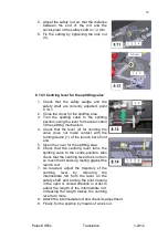
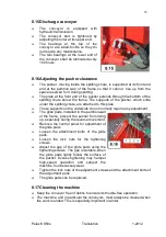
To  tighten  the  saw-chain,  loosen  the 
attachment  nuts  (1)  of  the  saw-bar  (Fig. 
8.1)  and  turn  the  tightening  bolt  (2) 
clockwise. 


To  remove  the  saw-chain,  turn  the 
tightening  bolt  (2)  counter-clockwise  until 
the chain slackens.                                                                                                          


The chain needs to be tightened enough 
to prevent it from sagging under the saw-
bar. 


Finally, tighten the attachment nuts of the 
saw-bar. 


Check  the  chain  for  tightness  at  regular 
intervals. 


Working with a blunt or damaged saw-chain is utterly uneconomical. Clean 
up and check the saw-chain. Make sure that there are no cracks in the chain 
links and that all the rivets are intact. If the chain is damaged or worn out, it 
must be replaced. 


8.1.2 Servicing the saw-chain 


If  the  saw-chain  will  not  be  used for  a  while,  clean  it  up  using  a  brush  and 
immerse it in oil or photogen. 


Always after re-sharpening, clean up the saw-chain thoroughly, remove from 
it any stuck chips or grinding dust and immerse it in oil. 

 
Cutting teeth 


Use only special saw-chain files! 


Saw-chain pitch 0.404"; gauge 1.6 mm; length 75 links. 


Checking  the  saw-chain  pitch:  t  =  the  distance  over  three  rivets  divided  by 
two. 


The standard filing angle is 30˚. 


The  angles  must  be  the  same  on  all  the  cutters  of  the  saw-chain.  If  the 
angles  are  uneven,  the  saw-chain  will  rotate  unevenly,  will  wear  more 
quickly and may even break. 


All cutters must be the same length. If the cutters are not the same length, 
they  will  have  different  heights.  This  makes  the  chain  run  roughly  and 
possibly crack. 


The  required  sharpening  results  can  be  met  only  after  sufficient  and 
constant practice. Use a file holder! As required, turn to a professional. 

 
Depth gauges 


The depth gauge determines the height at which the cutter enters the wood 
and  thus  the  thickness  of  the  chip  removed.  The  depth  gauge  setting  is 
reduced  when  the  chain  is  sharpened.  Use  the  filing  gauge  to  check  the 
setting. If necessary, file using a flat or triangular file. 


The  distance  between  the  depth  gauge  and  the  cutting  edge  =  0.65  mm. 
While  sawing  coniferous  trees,  the  setting  can  be  increased  by  0.2  mm, 
except in frost. 


Summary of Contents for KS 50s

Page 1: ...tor powered by electricity swing conveyor of 4 0 metres with hydraulic motor SERIAL NUMBER _______________________ YEAR OF MANUFACTURE _______________________ Palax Lahdentie 9 FI 61400 Ylistaro FINLA...

Page 2: ...Palax KS50s Translation 1 2012 II...

Page 3: ...g the discharge conveyor into the work position Figures 2 8 2 10 13 2 7 Bringing the conveyor into the transport position 14 2 8 Bringing the in feed conveyor to the work position Fig 2 1 14 2 9 Chang...

Page 4: ...gear oil Fig 8 2 26 8 3 Lubricating the machine 26 8 4 Coupling for electric motor Fig 28 26 8 5 Oil change 27 8 6 Maintenance of the valve 27 8 7 Detent end of valve 27 8 8 Lubricating the spool shif...

Page 5: ...For example the buyer of a tractor powered machine is expected to master the use of power take off shaft transmission Before the installation and operation the operator of the machine must become tho...

Page 6: ...r SERIAL NUMBER _______________________ We hereby certify that the machine meets the requirements of the Government Decree 12 6 2008 400 on safety of machinery through which the Machine Directive 2006...

Page 7: ...Palax KS50s Translation 1 2012 3 Martti Vaurio Managing Director...

Page 8: ...utting the maximum diameter of the tree is about 48 cm The maximum length of the log to be processed is 4 5 metres If the logs are longer than this a log deck shall be used 1 4 Warning signs Read the...

Page 9: ...away from moving parts The machine may only be operated by one person 1 5 Instruction signs Lifting point for a forklift truck Lifting point hook Direction of rotation of the motor Rotational speed of...

Page 10: ...conveyor Height adjustment of the discharge conveyor Starting and stopping the discharge conveyor belt Height adjustment of the splitting wedge Emergency stop only in machines powered by electricity...

Page 11: ...flap Flap not in use 1 7 Type markings Nameplate on the machine The name and address of the manufacturer Designation of the machine type Serial number and year of manufacture Total weight of the machi...

Page 12: ...n that of the tractor The machine may only be operated by one person The danger zone around the conveyor is 5 metres to the sides and to the rear Before transporting always swing the extension table o...

Page 13: ...break it Keep the working space clean and clear of foreign objects Always stop the machine before servicing Only cut one log at a time Danger Stay away from moving parts 1 10Noise emission and vibrat...

Page 14: ...aged during normal operation of the machine due to defects in material or workmanship The reasonable repair cost in accordance with the agreement between the seller and the manufacturer or the buyer a...

Page 15: ...ler immediately 2 2 Main parts of the machine Figs 2 1 2 2 2 3 and 2 4 1 Discharge conveyor 2 Winch 3 Cover for splitting area 4 Blade cover 5 Control panel 6 Controls for the starting stopping and em...

Page 16: ...ngth limiter 13 Crosscut saw blade 14 Log clamp 15 Saw chain oil tank 16 Log stop 17 Hydraulic oil tank 18 Oil cooler optional 19 Adjustment of oil flow to the saw chain 20 Exit opening for sawdust 21...

Page 17: ...ivered with the winch 2 4 Topping up hydraulic oil Fig 2 6 The volume of hydraulic oil is 120 litres Oil type Univis 32 SHELL Tellus 32 NESTE HYDRAULI 32 or equivalent Only use fresh clean oil because...

Page 18: ...position which means the conveyor belt is immovable 2 Lower the conveyor using the control lever on the control panel 3 Lift up the extension point A Fig 2 8 4 Lower the extension point B Fig 2 8 5 Th...

Page 19: ...extension part of the in feed conveyor to the transport position proceeds in the reverse order 2 9 Changing the splitting wedge Fig 2 11 As standard the machine comes with a splitting wedge that spli...

Page 20: ...cking screw of the splitting wedge rail 2 10Lifting and moving the machine Figures 2 12 2 13 2 14 Lifting the machine is allowed With a forklift truck by the lifting points A under the machine s frame...

Page 21: ...cting the operating mode powered by tractor or electricity Figures 3 1 and 3 2 The machine is equipped with a system to prevent simultaneous operation in two modes When the cover plate is shifted to t...

Page 22: ...tric motor powered machine The emergency stop is carried out by depressing the Emergency Stop button button B on the starter Release the button by turning and pulling up 3 6 Starting the electric moto...

Page 23: ...od processor by the log deck or the pile of logs to be split so that access to from and working with the machine is completely unobstructed A suitable distance from the log deck to the in feed conveyo...

Page 24: ...djusted by shifting the hydraulic log length limiter Unscrew the locking bolts B that keep the hydraulic valve C in position and shift the log stop to the desired length position 4 4 How the safety de...

Page 25: ...in feed conveyor to the front and to the left in direction A Fig 5 1 Lift up the log clamp by simultaneously pulling back the lever of the log clamp Lower the log clamp onto the trunk as soon as the h...

Page 26: ...the sawing movement by pulling the handle completely to the rear The lowering speed of the saw bar is automatically adjusted in accordance with the cutting speed of the saw chain Keep the lever in its...

Page 27: ...itting the log in eight ways A wedge splitting in 2 4 ways optional Using this wedge the log can be split in two ways a log at maximum 20 cm in diameter or in four ways A wedge splitting in 6 ways opt...

Page 28: ...wedge and retry the splitting using the manual control Changing the position of the log often helps If the log does not split turn the splitting lever to the right to reverse the cylinder and enable...

Page 29: ...ition OFF no automatic splitting will occur and the splitting must be launched manually The splitting is launched by turning the control lever 2 for the splitting mechanism momentarily to its extreme...

Page 30: ...mmerse it in oil Cutting teeth Use only special saw chain files Saw chain pitch 0 404 gauge 1 6 mm length 75 links Checking the saw chain pitch t the distance over three rivets divided by two The stan...

Page 31: ...ine See the service schedule Many of the bearings are lubed for life and do not need to be lubricated If a lubed for life bearing receives too much lubricant its gasket may get damaged NOTE If the mac...

Page 32: ...uire regular lubrication Lubrication of the valve is particularly important if the machine is left standing for several months If the parts of the detent have become rusty the machine will not operate...

Page 33: ...rubber of the spool shifter 2 Spray lubricant on both sides of the pin and down on the ball joint 3 At the same time check that the rubber is intact 8 9 Structure of the detent end and the correct or...

Page 34: ...ngs of the splitting valve The valve and linkage have been adjusted and test run at the factory The initial settings do not usually change so there is rarely any need for readjustment If parts of the...

Page 35: ...wn Note The machine must be switched off Lift up the crosscut saw bar slowly and note when the pendulum 1 Fig 8 9 by means of the pusher 2 pushes the launch rod 5 so far along that the splitting valve...

Page 36: ...tting valve is in the centre position 8 14 1 Adjusting the safety wedge and the safety shaft 1 Close the cover for the splitting area 2 Loosen the adjustment bolts for the safety wedge 1 and check tha...

Page 37: ...ntring the valve does not make contact with the turning device 1 of the launch bar s front end 5 Open the cover for the splitting area 6 Check that the centring lever turns the splitting valve to the...

Page 38: ...attached to this plate These supports on the underside do not normally require any adjustment The glide pads installed in the partition wall of the frame prevent the pusher from rising up especially...

Page 39: ...ing for a longer period of time Lubricate the machine after washing Note Do not direct the water jet onto electric devices or bearings 8 19Storing the machine The machine is intended for outdoor use b...

Page 40: ...Electric motor Cleaning X Electric equipment Cleaning X 10MALFUNCTIONS AND THEIR REMEDY Disturbance Cause Remedy Splitting is not operational 1 Protective net for splitting chute is open 2 No oil or t...

Page 41: ...an oblique position 1 Straighten the saw shaft and tighten the bolts The conveyor belt is running at the side 1 The setting has moved out of position 1 Adjust the return roller at the end of the conv...

Page 42: ...ng order 1 Switch the positions of two of the conductors in the plug Leave the work to an expert The oil gets very warm 1 Too little oil 2 The cylinder hits the bottom but the pressure is not relieved...

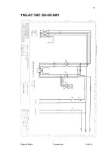
Page 43: ...Palax KS50s Translation 1 2012 38 11ELECTRIC DIAGRAMS...

Page 44: ...Palax KS50s Translation 1 2012 39...

Reviews: