background image

5

PZ Series 150-250-500-1000 Shaker Cleaner 

Portable collectors may require special installation 

accommodations.

Hoisting Information

Failure to lift the collector 

correctly can result in severe 

personal injury and/or property damage.
Use appropriate lifting equipment and adopt 

all safety precautions needed for moving and 

handling the equipment.
A crane or forklift and qualified operator are 

recommended for unloading, assembly, and 

installation of the collector.
Location must be clear of all obstructions, such 

as utility lines or roof overhang.

Use spreader bars to prevent damage to collector’s 

casing.
Check the Specification Control drawing for weight and 

dimensions of the collector and components to ensure 

adequate crane capacity.
Allow only qualified crane or forklift operators to lift the 

equipment.
Refer to applicable OSHA regulations and local codes 

when using cranes, forklifts, and other lifting equipment. 
Lift collector and accessories separately and assemble 

after collector is in place.
Use drift pins to align holes in section flanges during 

assembly.

Use all lifting points provided.
Use clevis connectors, not hooks, on lifting slings.

Collector Location

Pakzy equipment is not 

designed to support site installed 

ducts, interconnecting piping, or electrical 

services. All ducts, piping, or electrical 

services must be adequately supported to 

prevent severe personal injury and/or property 

damage.
When hazardous conditions or materials are 

present, consult with local authorities for the 

proper location of the collector.
Dust collection equipment may reach peak 

sound pressure levels above 80 dB (A). Noise 

levels should be considered when selecting 

collector location.

Locate the collector to ensure easy access to electrical 

supply, to simplify solids collection container handling 

and routine maintenance, and to ensure the straightest 

inlet and outlet ducts.
Provide clearance from heat sources and avoid any 

interference with utilities when selecting the location.

Standard Equipment

The collector has a high center-

of-gravity and may overturn if not 

secured properly.
Secure the collector to the lifting device.
Use care when moving the collector.

Unimaster dust collectors are delivered partially 

assembled. Collector installation, optional equipment 

assembly, and electrical connections are completed at 

the job site.

Anchors must comply with local 

code requirements and must be 

capable of supporting dead, live, wind, seismic, 

and other applicable loads.
Anchor sizes shown are provisional, as final 

anchor sizing will depend on jobsite load 

conditions, collector location, foundation/

framing design variables and local codes.
Consult a qualified engineer for final selection 

of anchors.

Hopper and Leg Installation

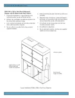
Reference Typical Foundation Anchor and leg assembly 

drawing shipped with the collector prior to starting 

assembly.

Summary of Contents for PZ Series

Page 1: ...rate or perform maintenance on this collector until you have read and understood the instruction and warnings contained within this manual PZ Series Dust Collector PZ 150 250 500 1000 Shaker Cleaner M...

Page 2: ...nt This manual has been supplied to assist with the installation operation and maintenance for the collector purchased Please read the manual before installing operating or performing maintenance on t...

Page 3: ...uipment 5 Hopper and Leg Installation 5 Provisional Anchor Bolt Recommendations 6 Collector Installation 6 Electrical Wiring 8 Inlet Assembly 8 Preliminary Start Up Check 12 Maintenance Information 13...

Page 4: ...1 Safety Communication...

Page 5: ...eration Other options include explosion relief vents static grounding weather hoods and caster frames Purpose and Intended Use Misuse or modification of this equipment may result in personal injury Do...

Page 6: ...et The Unimaster is an intermittent duty collector which means that cleaning starts when the fan is turned OFF and the appropriate fan run down time is complete The solid state timer automatically sta...

Page 7: ...ollector will compromise collector performance Inspect collector to ensure all hardware is properly installed and tight prior to operating collector Installation Use proper equipment and adopt all saf...

Page 8: ...ices must be adequately supported to prevent severe personal injury and or property damage When hazardous conditions or materials are present consult with local authorities for the proper location of...

Page 9: ...0 to 70 Hopper and 55 Gallon Drum Base Styles 1 Prepare the foundation or support framing in the selected location Locate and install anchors 2 Lift collector into position over the anchor bolts and l...

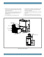
Page 10: ...bolts using customer supplied hardware Typical Installation PZ 500 to 1000 or Two Piece Shipment 5 Remove the lifting brackets from the top of the base assembly 6 Apply two strips of sealant or caulk...

Page 11: ...with back inlets Contact Pakzy if additional changes are necessary 1 Remove the inlet blank from the specified location 2 Replace damaged sealant if necessary 3 Secure inlet to collector using the ha...

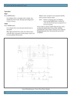
Page 12: ...nergized and the shaker motor runs for approximately 30 seconds Typical Wiring Diagram Three Phase Power Supply Shaker motor contactor is de energized and the timer resumes inactive status Note Before...

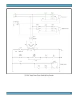
Page 13: ...10 230 Volt Single Phase Power Supply Wiring Diagram...

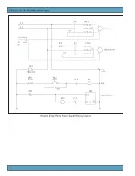
Page 14: ...11 PZ Series 150 250 500 1000 Shaker Cleaner 115 Volt Single Phase Power Supply Wiring Diagram...

Page 15: ...are properly wired and all service switches are in the OFF position 7 Check that all optional accessories are installed properly and secured 8 Turn power ON at source 9 Turn fan motor ON 1 Check all...

Page 16: ...ipment and procedures Note the standard collector is not equipped with access platforms unless noted on the specification drawings Electrical service or maintenance work must be performed by a qualifi...

Page 17: ...bag pockets into the shaker bar slots 6 Push the filter assembly the remaining distance into the collector and check that all pockets are firmly seated in the shaker bar 7 Lift retention handles for U...

Page 18: ...h and low pressure ports on the side of the gauges 3 Attach the mounting bracket using three 6 32 x 1 4 in screws supplied 4 Mount the gauge and bracket assembly to the supporting structure using two...

Page 19: ...dia bonding and grounding components are available for UMA collectors equipped with antistatic filter bags 1 If the collector is ordered with antistatic filter bags the grounding lug and internal comp...

Page 20: ...vented equipment outside buildings and away from normally occupied areas Explosion vents should be inspected regularly to confirm physical and operational condition Replace any damaged parts immediate...

Page 21: ...FF and allow the controller to perform several complete cleaning cycles Replace filter bags Motor speed low Check all supply voltage phase and motor connections Fan rotation backward Check and correct...

Page 22: ...______________________ Collected Dust _________________________________________________________________________ Dust Properties Kst_______________Pmax______________MIE____________MEC_________________...

Reviews: