December 22, 1997
Section 150-219-100-02
HDU-217/219 and
HCC-239 List
1
Page 15
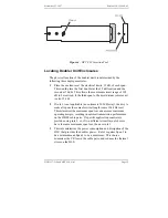
Figure 4. HCT-239 Insertion Tool
Locating Doubler Unit Enclosures
The physical location of the doubler units is determined by the
following three deployment rules:
1
Place the enclosures at the electrical limits, 35 dB, of each span.
This would place the first doubler at the 35 dB location and the
second at 70 dB. This allows the maximum circuit range of 105
dB to be realized, if the third span to the most distant remote unit
is also 35 dB.
2
If rule 1 is not applicable (no customers 105 dB away), then try to
make all spans the same electrical length (same 196 kHz loss).
This minimizes the maximum span loss and assures maximum
operating margin, resulting in optimal transmission performance
on the HDSL cable pairs. If specific application constraints
preclude using rule 2, or, if two different circuit layout choices
have the same maximum span loss, then use rule 3.
3
This rule minimizes the power consumption and dissipation of the
HLU that provides the doubler power. Rule 3 requires Span 1 to
be a minimum and Span 3 to be a maximum. This choice
minimizes the I
2
R loss in the cable pairs, and reduces the thermal
stress on the HLU.


