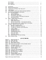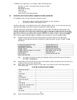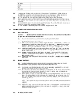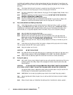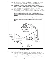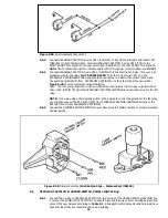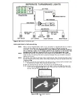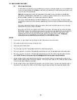
Headlights
Engine
Dash
Tail Lights
5.5
A good exercise is to lay out the wire harness on the floor beside your automobile and identify all the
SECTIONS. You will want to route the harness through and around open areas. Inside edges provide
protection from hazards and also provide places for tie wraps, clips and other support.
5.6
Route the harness away from sharp edges, exhaust pipes, and hood, trunk and door hinges.
5.7
Plan where harness supports will be located. Allow enough slack at places where movement could occur
(body to frame, frame to engine, etc.). Use a support every 12 inches unless the harness routes under the
floor carpet.
5.8
At wire ends don't depend on the terminals to support the harness. The weight of the harness could cause
terminals to disconnect or copper wire strands to break.
5.9
The wires should be bundled into groups. Use nylon ties, poly split loom, or tape.
6.0
HARNESS GENERAL INSTALLATION INSTRUCTIONS
6.1
Rough Installation
CAUTION:
DISCONNECT THE POWER FROM YOUR VEHICLE BY REMOVING THE NEGATIVE
(BLACK) BATTERY CABLE FROM THE BATTERY.
Note: Make no wire connections or permanent mounting of any kind at this time!
6.1.1
Position the fuse block in its mounting area.
6.1.2
Either use the included plate to cover the existing bulkhead hole or drill a 1-1/4" (1.25") hole near
the fuse block for engine and headlight group wires to pass through (ENGINE SECTION, ENGINE
SECTION A, SINGLE 10 GA. (Red wire #916), and HEADLIGHT SECTION A). If using the plate,
install it on the “engine side” of the fire wall using the self tapping screws provided.
6.1.3
Install the Firewall grommet in the plate or the new hole you drilled. Route engine and headlight
group wires through the grommet and position the harness groups in the areas decided upon in
Sections 5.3 and 5.1.
6.1.4
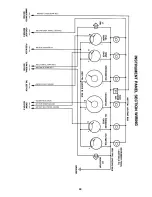
Route dash group (ACCESSORY SECTION B+, ACCESSORY SECTION SWITCHES, HEADLIGHT
SECTION B, INSTRUMENT PANEL SECTION and RADIO SECTION) upward to rear of dash and
temporarily tie in place.
6.1.5
Position rear group, consisting of theTAIL SECTION, on floor pan area decided upon in Sections
5.3 and 5.4.
6.2
Harness Attachment
Note: Harness routing and shaping is and should be a time-consuming task. Taking your time will
enhance the beauty of your installation. Please be patient and TAKE YOUR TIME!
6.2.1
Permanently mount the fuse block base with 2 self tapping screws supplied with this kit. (Note:
The fuse block itself does not have to be grounded.)
6.2.2
Mold harness groups to the contour of floor pan, firewall, fender panels, and any other area where
wires or harness groups are routed. Remember to route the harness away from sharp edges,
exhaust pipes, hood, trunk and door hinges, etc.
6.2.3
Attach harness groups to your automobile with clips or ties starting at the fuse block and working
toward the rubber grommet for the front groups and along the floor pan for the rear group. The
dash wires should be routed out of the way of any under-dash obstacles, such as cowl vent, air
conditioning, radio, etc.
Note: Do not tighten tie wraps and mounting devices at this time. Make all harness attachments
LOOSELY.
6.2.4
When used every 1-1/2" or so on the visible areas of the harness, the plastic wire ties make a very
attractive assembly. A tie installed in other areas every 6" or so will hold the wires in place nicely.
Remember to take your time!
7
6.3
Grounding the Automobile


