background image

7.3


Steering Column Wiring - Turn Signal Connections 

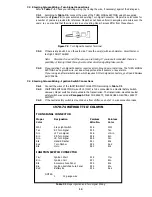
Refer to Table 7-1. Check your existing wiring (by tracing the wire, if necessary) against the data given. 

 
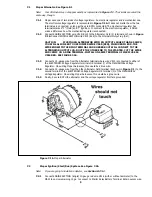
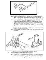
7.3.1  According to Table 7-1, connect the wires of the TURN SIGNAL SECTION using the supplied 

terminals (see Figure 7.3) to your automobile's existing Turn Signal Connector. Mopar wire color codes for 
a number of years are provided for reference. Mopar has not been uniform in assigning wire colors over the 

years; so you may find that the wire colors in your existing Mopar harness differ from those shown.  


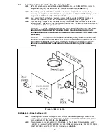
      Figure 7.3  Turn Signal Connector Terminal 


7.3.2  If there is any doubt, be on the safe side. Trace the wire(s) with an ohmmeter, circuit tester, or 

test light. DON'T GUESS! 


Note:   Disconnect one end of the wire you are tracing. If you leave it connected, there is a 

possibility of tracing it back through some other circuit and getting false results.


7.3.3


If your existing Turn Signal Connector requires a Horn Ground wire, install one. The TURN SIGNAL 

SECTION has no ground wire, nor does it support seat belt buzzers, or key alarms. 
If your using an aftermarket column which requires GM turn signal connectors, you’ll need Painless  

part #30806. 


7.4


Steering Column Wiring - Ignition Switch Connections 


7.4.1  Connect the wires of the IGNITION SWITCH SECTION according to Table 7-1
7.4.2  IGNITION SWITCH SECTION wire #919 (YLW) is to be connected to a Neutral Safety Switch. 

However, Mopar switches are mounted in the transmission. The transmission-mounted neutral 
safety switch was wired at Paragraph 7.2.4. FOR SAFETY, PLEASE USE A NEUTRAL SAFETY 

SWITCH! 

7.4.3


If the neutral safety switch is mounted on a floor shifter, see note 7 in wire connection index. 


Table 7-1 Mopar Ignition and Turn Signal Wiring 


 12 

1970-74 WITHOUT TILT COLUMN


TURN SIGNAL CONNECTOR 


Mopar   

Designation 


Painless 

Painless 

Color   


Wire No. 

Color 

 
Wht 


Stop Light Switch  


918 


Wht 

Tan 


RF Turn Signal 


925 


Tan 

Grn 


LF Turn Signal 


926 


Lt.Grn 

Brn 


RR Turn Signal   


948 


Brn 

Grn 


LR Turn Signal 


949 


Grn 

Blk 


Hazard Flasher   


951 


Blk 

Red 


Turn Flasher 


952 


Red 

Blk 


Horn 


963 


Blk 


IGNITION SWITCH CONNECTOR 


Ylw¹ 


Ignition Start 


919 


Ylw 

Brn 


Ignition Coil 


931 


Brn 

Blk 


Accessory Fuse Panel 


932 


Blk 

Blu 


Ignition Switched Fuse Panel 

933 


Blu 

Red 


Battery B+ 


934 


Red 


NOTES: 

1.


12 gauge wire 

Summary of Contents for 90542

Page 1: ...Wire Harness Installation Instructions For Installing 10127 Customizable Mopar Chassis Harness 21 Circuit Manual 90542...

Page 2: ...s please call or email us our contact information can be found at the top of this page or online at www painlessperformance com We sincerely appreciate your business Painless Performance Products LLC...

Page 3: ...tor Conversion 13 8 3 Connecting to Ammeter and the Maxi Fuse 14 8 4 Interior Lighting 14 8 5 Headlight Section A 15 8 6 Headlight Section B 16 8 7 Instrument Panel Wiring 16 8 8 Brake Light Switch 16...

Page 4: ...he different circuits during installation and later on if additions to the overall system are necessary For fuse specifications and wire color designations see Section 9 0 All wire is 600 volt 125 c T...

Page 5: ...g to the number Always pay special and careful attention to any Notes especially those in the Tables and any text marked Caution 3 0 CONTENTS OF THE PAINLESS WIRE HARNESS KIT Refer to Figure 3 1 to ta...

Page 6: ...Section 7 0 To help you begin thinking through the installation of your wire harness read the following sections 5 1 Familiarize yourself with the harness by locating each of the harness sections in...

Page 7: ...the Firewall grommet in the plate or the new hole you drilled Route engine and headlight group wires through the grommet and position the harness groups in the areas decided upon in Sections 5 3 and 5...

Page 8: ...Remember to allow enough slack in the harness and wires at places where movement could possibly occur such as automobile body to frame frame to engine etc Double check your calculations 6 4 4 Strip i...

Page 9: ...RUBBER BOOT WILL CONNECT TO THE ALTERNATOR OUTPUT LUG ROUTE THE OTHER END TO THE STARTER CUT THE WIRE AND CRIMP ON A RING TERMINAL INSTALL ON SAME TERMINAL OF MAXI FUSE AS 916 RED SEE FIGURE 7 1B 7 1...

Page 10: ...mount it away from other wiring or hoses The ballast resistor gets very hot during operation Connect ENGINE SECTION A wire 931 BRN to one end of the Ballast Resistor Connect the other end of the balla...

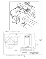
Page 11: ...Figure 7 2A Mopar Ignition Start Run System Figure 7 2B Mopar Electronic Ignition with Dual Ballast Resistor 11...

Page 12: ...r does it support seat belt buzzers or key alarms If your using an aftermarket column which requires GM turn signal connectors you ll need Painless part 30806 7 4 Steering Column Wiring Ignition Switc...

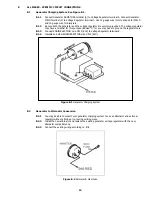
Page 13: ...his purpose labeled G or you may have to ground the regulator case 8 1 3 Connect ENGINE SECTION wire 915 BLK to Voltage Regulator terminal B 8 1 4 Insulate and stow ENGINE SECTION wire 914 BLU Figure...

Page 14: ...attery B terminal CAUTION BOTH AMMETER TERMINALS MUST ABSOLUTELY BE ISOLATED FROM GROUND IF EITHER AMMETER TERMINAL COMES IN CONTACT WITH GROUND A HARNESS FIRE IS INEVITABLE USE EXTREME CARE AND DILIG...

Page 15: ...nectors For models with separate high beam head lamps extra head lamp connectors have been supplied To make connections for separate high beam lamps run a jumper wire from the connection of wire 908 R...

Page 16: ...Note The wire going to the fan in Figure 8 4B will be coming from the fan relay output terminal Wire 901 GRY WHT from the ACCESSORY SECTION SWITCHES is an activation wire for the fan relay NOTE If you...

Page 17: ...ELOW Which diagram you will use depends on whether or not you have one bulb on each side of the vehicle that is for the brake tail and Turn Signal Lights this is referred to as integrated lights or yo...

Page 18: ...nto anything other than a grounded metal part then you will need to provide a separate ground wire 8 10 3 This kit has a bag containing 30 Mopar lamp socket terminals These terminals fit all lamp sock...

Page 19: ...from the fuse panel and certain other wires such as those originating from the horn relay the dimmer switch and the instrument panel section These pre connected wires are identified by an asterisk in...

Page 20: ...el Section Gry Blk1 18 923 Tachometer Source Tachometer Instrument Panel Section Red 18 954 Electric Choke Fuse Panel Fuse Panel HEADLIGHT SECTION A Grn Red1 14 924 Horn B Horn Relay Fuse Panel Tan 18...

Page 21: ...rn Signal Section Blu 18 939 Fuel Sending Unit Fuel Gauge Instrument Panel Section Blk 14 929 Tail Lights Headlight Switch Headlight Section B Orn 18 950 Third Brake Light Turn Signal Switch Turn Sign...

Page 22: ...22...

Page 23: ...23...

Page 24: ...original purchaser to be free from defects in material and workmanship under normal use Painless Performance will repair or replace defective products without charge during the first 12 months from t...

Reviews: