background image


13

instructions on how to remove this component). 

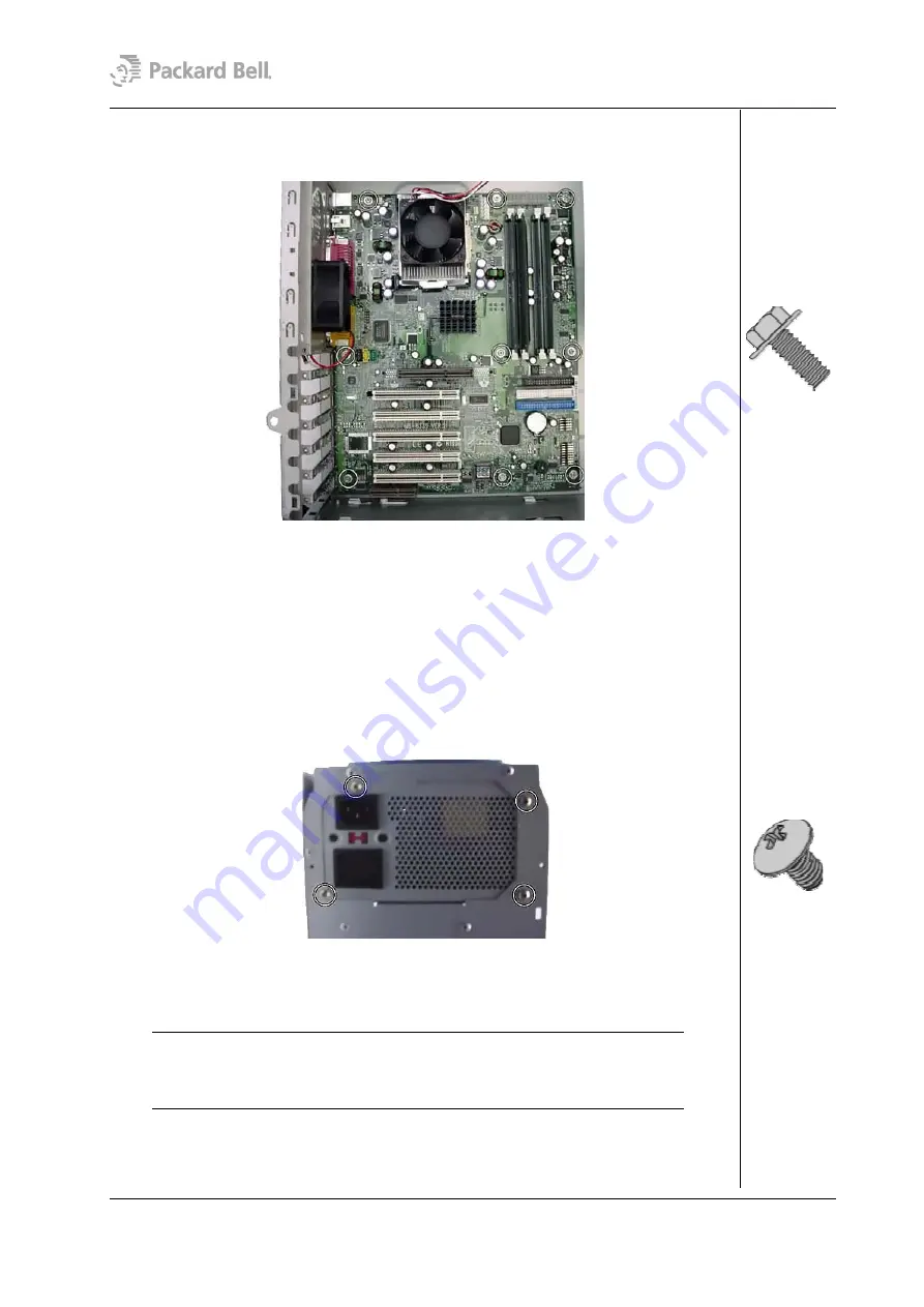
3.  Remove the screws that hold the motherboard in place and carefully take out the 

motherboard from the chassis. 


Fig. 22:  

Removing the screws of the motherboard


Removing the Power Supply 

To remove the power supply unit, first remove the rear bezel (see section 

Removing the 

Rear Bezel

) and remove the side cover (see section 

Removing the Left Side Cover

); then 

follow the steps below: 
 

1.  Place the chassis on its side, with the motherboard at the bottom. 
2.  Disconnect the power supply cables from all peripherals and the motherboard. 
3.  Remove the screws that secure the power supply unit to the back of the chassis. 


Fig. 23:  

Removing the power supply unit screws 


4.  Carefully lift the power supply out of the chassis. 


Note:   

When reassembling the power supply unit, make sure that the voltage 

selector switch is set correctly before connecting the system to a power strip (surge 
protector) or grounded AC electrical outlet. If the switch is set incorrectly, the system 
could become seriously damaged. 


Packard Bell Stella (iXtreme) Disassembly Manual 

Summary of Contents for Stella

Page 1: ...Packard Bell Stella iXtreme Disassembly Manual...

Page 2: ...the Right Side Cover 5 Removing the Front Bezel 5 Removing the Drive Bracket 6 Removing the DVD CD ROM Drive 7 Removing the Floppy Disk Drive 7 Removing the Hard Disk Drive 8 Removing Add In Cards 9...

Page 3: ...rinted wiring board Improper repairs can create a safety hazard Any indication of component replacement or printed wiring board modifications may void any warranty or exchange allowances Disassembly I...

Page 4: ...Supply Unit Under no circumstances should you attempt to disassemble the power supply The power supply contains no user serviceable parts Inside the power supply are hazardous voltages that can cause...

Page 5: ...the chassis and carefully pull the bezel away from the chassis Fig 1 Removing the rear bezel Removing the Left Side Cover To remove the left side cover first remove the rear bezel see section Removing...

Page 6: ...centimetres towards the front of the chassis 3 Lift the side cover out and away from the chassis Removing the Front Bezel To remove the front bezel first remove the rear bezel see section Removing the...

Page 7: ...t bezel see section Removing the Front Bezel then follow the steps below 1 Disconnect all power and data cables from the drives installed Fig 5 Disconnecting power and data cables 2 Remove the screw t...

Page 8: ...ve in the bay Fig 8 Removing the DVD CD ROM drive screws 3 If required remove the screws on the right side as well 4 Slide the drive towards the front out of the bay Removing the Floppy Disk Drive To...

Page 9: ...ft side cover see section Removing the Left Side Cover remove the front bezel see section Removing the Front Bezel then follow the steps below 1 Carefully disconnect the four wire power cable and the...

Page 10: ...r then follow the steps below 1 Disconnect all cables from the add in card to be removed 2 Press the two metal clips until the retention bracket unlocks and remove the bracket Fig 13 Remove the retent...

Page 11: ...ssembly Fig 15 Removing the switch LED assembly 3 Gently pull away the cable and the switch LED assembly from the chassis Note When reassembling the switch LED assembly take care that you return it to...

Page 12: ...m IV please perform this additional step 1 Remove the CPU heat bracket by removing the four screws Fig 18 Removing the CPU heat bracket Removing the System Fan To remove the optional system fan first...

Page 13: ...cover see section Removing the Left Side Cover remove all add in cards see section Removing Add In Cards remove the CPU see section Removing the CPU and or the section Removing the Pentium 4 CPU remo...

Page 14: ...chassis on its side with the motherboard at the bottom 2 Disconnect the power supply cables from all peripherals and the motherboard 3 Remove the screws that secure the power supply unit to the back o...

Page 15: ...RIAL Copyright 2002 NEC Computers International BV All rights reserved Packard Bell is a trademark of NEC Computers International BV The names of actual companies and products mentioned herein may be...

Reviews: