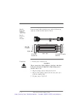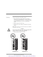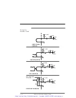
Cabling
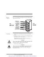
diagram
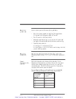
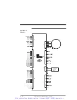
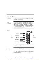
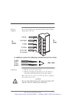
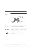
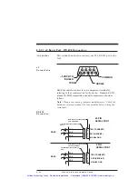
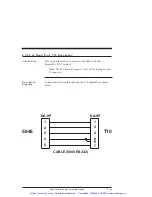
The colors referenced in the diagram follow the Pacific Scientific
stepper motor color code.
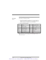
Procedure
1. Strip the wires so that the twisted ends will be the length
shown.
2. Referring to the diagram, twist the striped and solid lead ends
and attach the wires to the connector.
Note: Make sure the screws on the PCD connector are
tightened down firmly on the wiring.
CAUTION
Do not pre-tin (solder) the tips of the cables going into the PCD
connector. This can result in a loose connection.
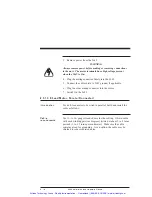
3. Remove power from the 5645.
WARNING
Always remove power before making or removing connections
to the unit. The motor terminals have high voltage present
when the 5645 is On.
TO
DRIVE
TO
MOTOR
A(BLACK)
(ORG/WHT)
1
.27 in
(7 mm)
.27 in
(7 mm)
.27 in
(7 mm)
.27 in
(7 mm)
.27 in
(7 mm)
2
3
4
5
B(RED)
(YEL/WHT)
B(YELLOW)
(RED/WHT)
GND(GREEN)
A(ORANGE)
(BLK/WHT)
5645 Installation and Hardware Manual
2 - 17
Artisan Technology Group - Quality Instrumentation ... Guaranteed | (888) 88-SOURCE | www.artisantg.com


