


SECTION 3 INSTALLATION
51
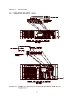
3.3.4 INPUT VOLTAGE CONFIGURATION, MODELS 140, 160, 345, AND 360-ASX
The 140-ASX, 160-ASX, 345-ASX, and 360-ASX Power Sources have been designed to accept
most standard three phase input voltage forms. This is accomplished through the use of a tapped
input power transformer. Configuring the proper input form is simply a matter of setting jumpers in
the appropriate positions. The system is designed for use with input frequencies of 47 to 63 Hz.
(Optionally, systems may be used with input frequencies of up to 440 Hz. Contact the factory for
details.)
Figure 3.3.4 shows the location of the various jumpers which need attention relative to input voltage
form. The position of these jumpers is listed on the accompanying table.
The first step in configuring the input power form is to remove the top cover. Next, connect the
jumpers as stated in the table for the desired input voltage. Refer to the table in Figure 3.3.4 for the
proper setting.
After configuring the input voltage form, check connections and insure that they are tight and in the
correct position. Replace the top cover.
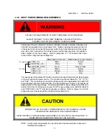
CAUTION
CONNECTION OF THIS UNIT TO IMPROPER INPUT VOLTAGES WILL CAUSE
CATASTROPHIC DAMAGE TO THE POWER SOURCE.
READ THE INPUT VOLTAGE LABEL AND CONNECT TO THAT INPUT VOLTAGE ONLY. IF
THERE ARE ANY QUESTIONS, CONTACT THE FACTORY.
.
The 140-ASX, 345-ASX, or 360-ASX is then connected to an appropriate distribution panel via the
input power cord. Refer to Paragraph 2.1.1 for minimum input service requirements of the various
input voltage forms.
WARNING
DISCONNECT THIS UNIT FROM THE INPUT SERVICE BEFORE REMOVINGTOP COVER.
HIGH VOLTAGE HAZARD PRESENT INSIDE UNIT WHEN TOP COVER IS REMOVED AND STILL
CONNECTED TO INPUT SERVICE


