background image

10  

©PACIFIC ENERGY FIREPLACE 
PRODUCTS LTD.

Warning: 

Under no circumstances is this heater to be installed 

in a makeshift or "temporary" manner. It may be fired only 
after the following conditions have been met.

*   DO NOT ATTEMPT TO CONNECT THIS HEATER TO 

ANY AIR DISTRIBUTION DUCT.

*  Do not connect this unit to a chimney flue serving another 

appliance. 

*   Outside combustion air or fresh air into the room may be 

required in your area, consult local building codes (see 
Combustion Air section).

- The services of a competent or certified installer, (certified 
by the Wood Energy Technical Training program (WETT) - in 
Canada,or the Hearth Education Foundation (HEARTH) - in 
U.S.A.,) are strongly recommended.

BOTH CHIMNEY SYSTEM AND CONNECTOR MUST BE 
6"(150mm) DIAMETER AND LISTED TO: IN CANADA -  
ULC S-641 LISTED CONNECTOR AND ULC-S-629 LISTED 
CHIMNEY, IN USA -  UL-103 HT LISTED CONNECTOR 
AND CHIMNEY

Clearances

1.  This heater may be installed using a single-wall connector 

(smoke pipe) or listed double-wall connector (see Mobile 
Home installation).

2.  Clearances to combustible surfaces and materials using 

single-wall connector are shown in Figure #6, page 11.


Clearances may be reduced with various heat insulating 
materials. Consult local fire codes and authorities for 
approval.

3.  Alternately, for close clearances, use a listed double-wall 

connector.  See Fig #6 page 11.

It is possible to store wood between the stove supports, 
underneath the unit but not recommended. The wood must 
not extend further forward than flush with the supports. 

NOTE: Refer to local fire codes, CAN-B365 in Canada and 
NFPA 211 in the U.S..

Chimney and Connector

Connect to a listed chimney or a chimney suitable for use 
with solid  fuel that is lined and in good condition. Chimney 
flue exit is to be 3 feet (1 m.) above roof and two feet (0.6 m.) 
above highest projection within 10 feet (3 m.). The installation 
must meet all local codes. Minimum system height is 15 feet 
(4.6 m.) (measured from base of appliance).

*   The chimney connector should not pass through an attic, 

roof space, closet or similar concealed space, floor, or 
ceiling.  Where passage through a wall, or partition of 
combustible material is desired, the installation shall 
conform to CAN/CSA-B365, Installation Code for Solid-
Fuel-Burning Appliances and Equipment in Canada or  
NFPA 211: Standard for Chimneys, Fireplaces, Vents, and 
Solid Fuel-Burning Appliances in the U.S.A..

Double-Wall Connector

-  Use a listed double-wall connector.(listed to ULC S641)
-  Install all components to the chimney connector 

manufacturer's installation requirements.

Single-Wall Connector(smoke pipe)

Smoke pipe must be:
*   as short and straight as possible, use six inch 
 

diameter, 24GA or thicker black pipe that is clean and in 
new condition.

*    secured at every joint and collar with 3 sheet metal screws.
*   installed with the crimped or male ends pointing down.  

This will carry any liquid creosote or condensation back 
into the stove.

Procedure

1.  If a listed chimney and double-wall connector is to be 

connected to the stove, install all components to the 
chimney manufacturer's installation requirements.

2.  If a roof or ceiling support is used in the installation, you 

will find the chimney manufacturer's complete instructions 
packed with the roof support.

3.  If it is desirable to use smoke pipe in conjunction with the 

insulated chimney, see step 4.

4.  To start installing smoke pipe (chimney connector), slip 

crimped edge of the pipe inside the stove collar.  Use 
holes provided in collar to secure pipe with three screws.

5.  Install the remaining lengths of pipe one on top of the 

other to the finished height of the chimney connector up 
to the start of the chimney and secure to each other.

(Outside combustion air may  be required, consult local 

building codes.  See Combustion Air section on page 9.)

NOTE:

 Longer chimney lengths and different pitch flashings 

may be used. All other parts installed must be listed(see 

Figure #8, Page 12). Install all components to the connector 

and chimney manufacturer's installation requirements. Consult 

your chimney supplier for additional installation advice.

Residential Installation

310316-24

Summary of Contents for NEO 2.5

Page 1: ...ctions Contact local building or fire officials about restrictions and installation inspection requirements in your area IMPORTANT THESE INSTRUCTIONS ARE TO REMAIN WITH THE HOMEOWNER MODEL NEO 2 5 SER...

Page 2: ...Blower Operation 15 Optional Outside Air Adaptor 15 Troubleshooting 16 Replacement Parts NEO 2 5 17 Understanding Operating Your Pacific Energy Stove 18 Firebrick Installation Instructions 19 Label 2...

Page 3: ...ldup Chimney Fires The result of excessive creosote buildup is a chimney fire Chimney fires are dangerous Chimney inside temperatures can exceed 2000 F 1093 C This causes much higher than normal tempe...

Page 4: ...er no circumstances should you attempt to barbecue in this heater How to Test Your Wood Add a large piece of wood to the stove when it has a good large bed of coals It is dry if it is burning on more...

Page 5: ...dfurtherforward thanflushwiththepedestals Donotstorepaperorotherstove lighting devices within the pedestal area Although storing wood under the unit is possible it is not recommended NOTE Refer to loc...

Page 6: ...ur dealer Use 18 457mm x 10 1 4 260mm x 5 mm Ceramic glass only Do not substitute with any other type To remove broken glass remove the door gasket and then undo the eight screws securing the gasket g...

Page 7: ...ube in the back of the firebox Back side of airwash chamber located in the upper front of firebox Baffle locking pin Boost tube cover located in center of manifold bottom front of firebox When Cleanin...

Page 8: ...hold down brackets away from the stove Side Panel Removal Installation 1 To remove the panels first remove the screws that secure the panel to the rear shield Fig 3 2 Disengage the the tabs in the fr...

Page 9: ...raw outside air from behind the stove an outside air adaptor may be required see Optional Blower section Cut or drill a 4 102mm hole through a wall behind the unit Use an appropriate household 4 102mm...

Page 10: ...ance The chimney connector should not pass through an attic roof space closet or similar concealed space floor or ceiling Where passage through a wall or partition of combustible material is desired t...

Page 11: ...arance to Combustibles 6 Cut a hole in the ceiling and roof to suit the chimney system and frame in the sides The chimney support is mounted to the framing 7 Assemblechimneysectionssothefinishedlength...

Page 12: ...r 48 1219 mm 3 914 mm Minimum Hooded vent or 90 elbow turned down The chimney may incorporate an offset To do this safely all sections of listed connector offset elbows and chimney section must be scr...

Page 13: ...7 2 1m Ceiling Height Non combustible floor protector 48 1219 mm Hooded vent or 90 elbow turned down Ensure that the Masonry chimney meets all National Fire Protection Association and local building c...

Page 14: ...ce FIG 9 Mobile Home Installation Procedure CAUTION THESTRUCTURALINTEGRITYOFTHEMOBILE HOME FLOOR WALL AND CEILING ROOF MUST BE MAINTAINED The services of a competent or certified installer certified b...

Page 15: ...o turn on as the stove heats up to operating temperature It will also shut the blower off after the fire has gone out and the unit cooled to below a useful heat output range Manual Tomanuallyoperateth...

Page 16: ...ve Creosote Buildup See 1 2 3 above Low Heat Output 1 Wood is wet Use dry wood 2 Fire too small Build a larger fire 3 Draft too low Chimney plugged or restricted inspect and clean Won t Burn Overnight...

Page 17: ...NE16 7817 10 Side Shield Bracket LHS NE25 78485 All parts may be ordered from your nearest Pacific Energy dealer Use www pacificenergy net for the location of the dealer nearest you 10b Side Shield Br...

Page 18: ...design Traditionalwoodstoveshadabasiccombustionsystemwhich allowed a considerable amount of heat energy to escape up the chimney as unburned gases and particulates smoke PacificEnergyhasdesignedasyst...

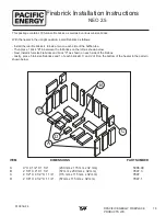
Page 19: ...ckage contains 18 full size firebricks as well as 6 various cut size bricks With the heater in the upright position install firebricks as follows Install the rear firebricks 4 full size two on each si...

Page 20: ...correctly at installation Any part that shows in our judgment evidence of defect shall be repaired replaced or refunded at Pacific Energy s option The defective part may be required to be returned to...

Page 21: ...21 PACIFIC ENERGY FIREPLACE PRODUCTS LTD 310316 24...

Page 22: ...22 PACIFIC ENERGY FIREPLACE PRODUCTS LTD 310316 24...

Page 23: ...DE LA CONSTRUCTION OU DE SERVICE D INCENDIE POUR DES INFORMATIONS QUANT AUX RESTRICTIONS PERMIS D INSTALLATION ET INSPECTIONS DANS VOTRE R GION NE RELIEZ PAS CET APPAREIL UN CONDUIT DE CHEMIN E DESSER...

Page 24: ...PACIFIC ENERGY FIREPLACE PRODUCTS LTD 2975 Allenby Rd Duncan B C V9L 6V8 For technical support please contact your retailer Web site http www pacificenergy net Printed in Canada...

Reviews: