


6
GAS SUPPLY
Caution: The gas line should be installed by a qualified
service person in accordance with all building codes.
Consult local and/or national building codes before
proceeding.
Correct gas line diameter must be used to assure proper
operation. The gas control is equipped with a captured screw
type pressure test point, therefore it is not necessary to provide
a 1/8 inch N.P.T. plugged tapping pressure test port for
checking gas pressure immediately upstream of the gas
supply connection to the appliance.
The gas valve inlet accepts a 3/8" N.P.T. fitting. For leg model
units, it is recommended to use the optional flex gas connector
(#GASC.GASCON). Route the gas connector inside the
adapter to the rear. Fasten connector to the right side near the
back with the bracket. Alternately, the gas supply line may
enter through the 4" diameter hole located in the base of the
leg adapter. This will allow the installation of the optional
blower kit.
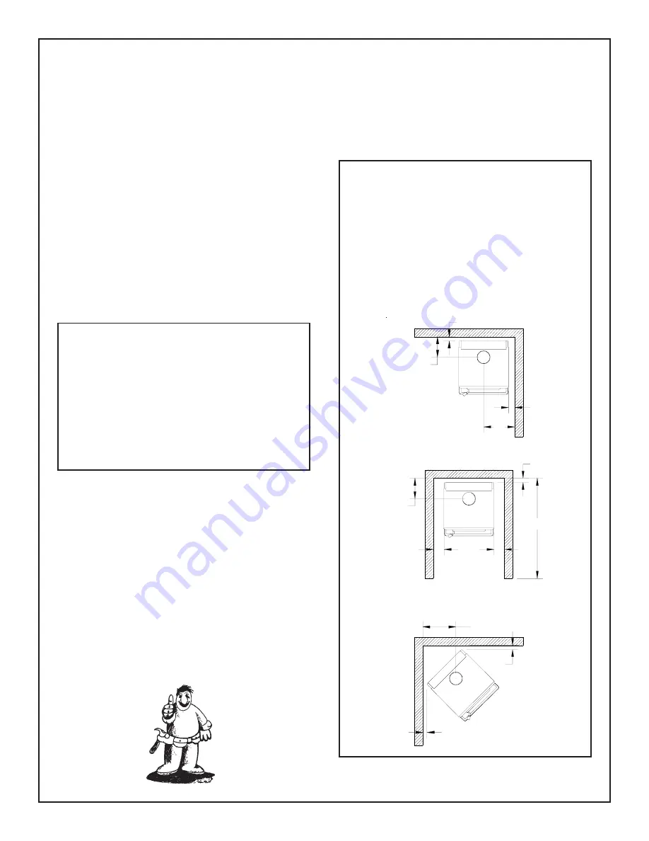
CLEARANCES
The minimum clearances from the appliance to combustibles
are shown on Fig. #4. Adequate clearances around air
openings and combustion air supplies are required.
FLOOR PROTECTION
Both, the Classic Gas and Super 27 Gas Heaters, may be
installed directly on a combustible floor. If the appliance is to
be installed directly on carpeting, combustible floor tile or
other combustible material other than wood flooring, the
appliance shall be installed on a metal or wood panel
extending the full width and depth of the unit.
ATTACHMENT TO FLOOR
Mobile Home installations require that the appliance be firmly
attached to the structure. Once the appliance is in it's final
location, secure the unit in place through holes in the pedestal
base. The holes are located on the left and right hand side of
the base.
Natural Gas
Propane
Min. Pressure
5.0" wc
11.5" wc
(For purpose of input adjustment)
Max. Pressure
10.5" wc
13.0" wc
Manifold Pressure
Maximum
3.8" wc
11.0" wc
Minimum
1.1" wc
2.9" wc
Correct gas pressure requirements:
Sidewall to Appliance
3 in.
(76 mm)
Rearwall to Appliance
2 in.
(51 mm)
Corner to Appliance
2 in.
(51 mm)
Alcove sidewall to Appliance
5 in.
(127 mm)
Alcove minimum width
34 in.
(864 mm)
Alcove maximum depth
48 in.
(1.2 m)
Alcove minimum height
61 in.
(1.5 m)
Minimum Clearance
to Combustibles
Fig. # 4
61" M INIM UM
ALCOVE HEIGHT
2"
9 3/4"
3"
2"
15"
5"
5"
2"
2"
15 3/4"
48"
9 3/4"


