


Part 1 – Introduction
15
Rear Panel Connections
Monitor Connection
Connect to the
VGA OUT
or
HDMI
port.
VGA OUT
HDMI
Audio Connection
AUDIO IN
AUDIO OUT
Connect the audio device to the
AUDIO IN
port and
speakers with a built-in amplifier to the
AUDIO OUT
port. Use the
AUDIO OUT
port to listen to audio from
network cameras.
Use the
AUDIO IN
port to establish two-way
communication with cameras.
Ř
This NVR does not feature a built-in audio amplifier
unit and therefore requires the user to purchase a
speaker system with a built-in amplifier separately.
It's possible to connect an amplified audio source
to the NVR, but microphones that do not have
a built-in amplifier will not function properly if
connected to the NVR directly. If this is the case,
connect the microphone to the NVR via a pre-
amp.
Ř
Check your local laws and regulations on making
audio recordings.
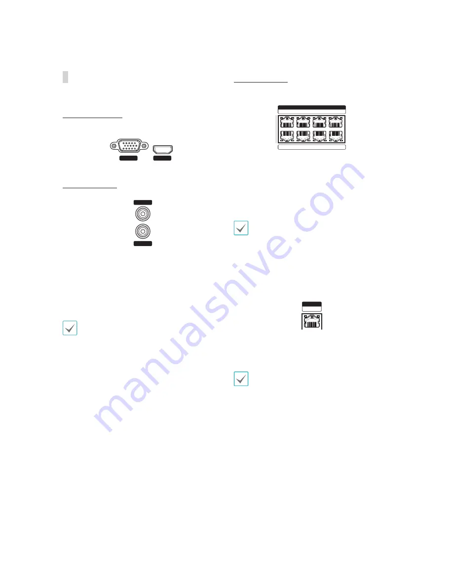
Video Connection
s
Video In/PoE Port
V
I
DEO
I
N
/ Po
E
A
C
E
G
B
D
F
H
Connect network cameras to the NVR using RJ-45
cable (Cat5, Cat5e, or Cat6). In addition to cameras,
you can connect external hubs (Optional: SmartIP-
SW2112PF, SmartIP-SW2128PF) to form a network.
The NVR recognizes DirectIP™ network cameras
automatically. Ports A through H support PoE.
s
We recommend that you use the Ext. port for
connecting to an external hub and using features
such as camera alignment.
s
Green LED on the right will turn on when PoE
comes on line. Orange LED on the left will then
flash once a link has been established.
s
Video In / Ext. Port
V
I
DEO
I
N
Ex
t.
This port does not support PoE. It's possible to
establish a network with network cameras and
external hubs using Cat5, Cat5e, and Cat6 cables.
Green LED on the right will turn on if connected to a
1000 BASE-T network. Orange LED on the left will
then flash once a link has been established.