background image


21

THE PACEMASTER PLATINUM PROCLUB CONTROL PANEL (cont’d)


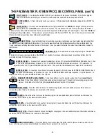
Calories
Distance
Aerobic Pts

RESULTS BUTTON – 

1)


Prior to beginning your workout, press this button to see the predicted caloric expenditure, Aerobic 

Points or distance for the workout you have chosen.  2) During your workout, press this button to select the desired feedback you want 

displayed; Calories, Aerobic Points, or Distance. 3) Press this button to change between English units and Metric units.  For details, refer 
to the METRIC UNITS section in this manual.  


EMERGENCY STOP BUTTON – 

Pressing this button during operation will stop[ the tread belt and reset the display.  This 

button is for 

EMERGENCY USE ONLY.


DISPLAYS 


TIMER –

 This window displays the chosen workout time in minutes and seconds (mm:ss) up to 59 minutes and 59 seconds. Times of 1 

hour to a maximum of 4 hours are displayed as hours and minutes (

– 

h: mm), with the dash as the first digit.  For example, one hour and 15 

minutes is displayed as 

-1:15

. In QUICK START, the TIMER will count up, displaying the elapsed time.  In all other program modes, the 

TIMER will count down, displaying the remaining time.  If a Warm Up and/or Cool Down mode is chosen, the TIMER will display as a 2 ½-
minute countdown for the warm up phase, a countdown for the main exercise phase and then a 2 ½ -minute countdown for the cool down 

phase.  


PROFILE –

 This window displays the program PROFILE of the chosen Conditioning, Stamina, Interval or Weight Loss program.  


In Quick 

Start, the PROFILE displays a quarter mile track.  In a Timed (Manual) program, the PROFILE displays a OneLap track.  For details, refer 
to the OneLap Track section in this manual. 


TOP CENTER –

1) This display will show lap # during the Quick Start workout and/or heart rate if chosen.


RESULTS –

1) Prior to pressing the START button, the Results window will display the predicted caloric expenditure, Aerobic Points or 

Distance for the workout you have chosen. 2) During the workout, this window can display calories expended, Aerobic Points or Distance.  

The current result displayed in this window will be indicated by an illuminated LED light.    


SPEED


 This window displays SPEED from 0.5 mph to 12.0 mph. prior to beginning a workout, the starting SPEED is displayed.  Once 

your workout has begun, the current SPEED is displayed.   


INCLINE –

 This window displays INCLINE from 0% to 15.0%. Prior to beginning a workout, the starting INCLINE is displayed.  Once your 

workout has begun, the current INCLINE is displayed. 


INDICATOR LED LIGHTS 


Set Weight –

 Within seconds of the magnetic safety key being inserted, the SET WEIGHT LED indicator light flashes and the last entered 

weight appears in the INCLINE display window.  Weight can be adjusted by pressing the INCLINE 

or 

buttons.  Once your weight is 

displayed, press PAUSE (ENTER). 


INCLINE Max –

 The INCLINE Max LED indicator light is illuminated when a Conditioning, Stamina, Interval or Weight Loss program  is 

selected. The number displayed in the INCLINE display window is the maximum incline that will be encountered for the program and level 

chosen. 


SPEED Max –

 The SPEED Max LED indicator light is illuminated when a Conditioning, Stamina, Interval or Weight Loss program is 

selected. The number displayed in the SPEED display window is the maximum speed that will be encountered for the program and level 

chosen. 


WARM UP and COOL DOWN – 

The WARM UP and/or COOL DOWN indicator LED lights will flash in the PROFILE display window when 

a WARM UP and/or COOL DOWN mode is selected.  

Summary of Contents for Platinum ProClub

Page 1: ...PaceMaster Platinum ProClub OWNER S MANUAL Manufactured by PaceMaster LLC 34 Fairfield Place West Caldwell NJ 07006 973 276 9700 www pacemaster com Part TMP1638 Rev 09 16 10 ...

Page 2: ...l 24 Using the Programmed Workouts 25 Programmed Workout Profiles 26 Using a wireless chest strap transmitter 27 Using the Contact Heart Rate Feature 27 EXCLUSIVE PACEMASTER FEATURES 28 29 Exercise Preview 28 Aerobic Points 28 Personal Electronic Trainer 28 29 CARE MAINTENANCE 30 31 Deck and Tread Belt Cleaning 30 Contact Heart Rate Sensor Cleaning 30 Lubrication 30 Centering the Tread Belt 31 TRO...

Page 3: ...mation DANGER CAUTION or WARNING indicates important safety warnings throughout the manual Failure to read and understand these warnings may result in personal injury or damage to your treadmill Tip indicates a useful suggestion when installing maintaining or using your treadmill Your PaceMaster treadmill is capable of varying your workout by changing speed incline and time It can also measure the...

Page 4: ...achments not recommended by PaceMaster LLC Never operate your PaceMaster treadmill if it has a damaged cord or plug if it is not operating properly if it has been dropped or damaged or if it has been immersed in water Should any of these occur contact your authorized PaceMaster retailer or service center for examination or repair Keep the cord away from heated surfaces Never drop or insert any obj...

Page 5: ...t the contents of the package match the hardware legend included in the hardware package If any parts are missing contact the authorized PaceMaster retailer where you purchased your PaceMaster treadmill Side Rail Left and Right Hardware Kit Owners Manual Control Panel Front Control Panel Back Motor Cover Ergo Bar Panel Support Tube Left and Right Treadmill Base Chest strap Upright Assembly ...

Page 6: ...equipment grounding conductor and a grounding plug The plug must be plugged into an appropriate outlet that is properly installed and grounded in accordance with all local codes and ordinances See example to the right WARNING Improper connection of the equipment grounding conductor can result in a risk of electrical shock Check with a qualified electrician or serviceman if you are in doubt as to w...

Page 7: ...ar bon to its mounting brackets cas shown in the figure The mounting brackets cmust slide inside the handle bar b 1 2 With the handle bar in place LOOSELY install eight 3 8 16 x 3 4 button head screws dwith 3 8 washers einto both handlebar uprights as shown The following must be done in the order it is written Tighten the screws labeled A and then B ...

Page 8: ...r bolted in place plug the black wire harness A into the socket B on the power supply board Twist open the purse lock clip at C insert the wire harness A confirm the wire harness is positioned as shown at point B and twist close the purse lock clip Follow the same procedure for purse lock clip D Step Three 3 1 Remove the Hex bolts kfrom both ends of ergo bar j Set aside D C A B 10 9 10 ...

Page 9: ... yet 4 3 Place the ergo bar jbetween the panel support tubes f and ias shown in FIG 2 Make sure the pin on the left panel support tube fis in the notch of the ergo bar Loosely attach ergo bar jwith the two Hex bolts kfrom Step 3 Do not tighten yet 4 4 Loosely install Bolt D a 20 x 1 Hex Bolt gthrough both CHR ground terminals and then a washer h Do not tighten yet 4 5 Proceed to tighten the ergo b...

Page 10: ...and rest in front of the cross brace as shown in the image below 5 2 Route the Contact HR wires in front of the cross brace 5 3 Lower control panel lonto the panel support tubes fand i Assembly with four 8 x 1 5 pan head screws tubes m Start with the screws labeled A and then proceed to B Note Make sure you do not pinch the wire harness Wire Harness Contact HR Wires ...

Page 11: ... display board Pull the wire harness taut then apply one piece of tape exactly as shown 5 2 Route the Contact heart rate wires as shown below Plug the CHR wires to CHR module Place a piece of tape directly over the blocks in the wires exactly as shown Note Make sure wires are inside panel Wire Harness Contact HR Wires Contact HR Module Make sure wires are inside panel ...

Page 12: ...ED 2 pieces of tape with backing T TAPE APE Magnetic Safety Key 1 ASSEMBLY INSTRUCTIONS cont d Step Seven Tape the magnetic safety key z to the control panel back nexactly as shown Note You will have 1 extra piece of tape ...

Page 13: ...MBLY INSTRUCTIONS cont d Step Eight Screw together the two halves of the control panel land nusing the ten 1 inch pan head screws o Start with the screw labeled 14 and proceed in a clockwise tightening sequence Note Make sure you do not pinch the wire harness ...

Page 14: ...ide the side rail adaptors rall the way onto the square handle bar support tube 9 2 The side rails are labled left pand right q slide the side rails over the side rail adaptors on their respective sides The grip on the side rail must slide completely inside the control panel ...

Page 15: ... Ten 9 1 Insert slotted head bolt sthrough the hole in the bottom of the side rail q Slide the side rail mounting bracket ton to the bolt as shown Push the slotted head bolt through the frame rail until it is protruding through the other side 9 2 Install the fender washer uand the kep nut v on the threaded end of the bolt Tighten the nut vas shown 9 3 Repeat this step for the other side rail ...

Page 16: ...il must slide completely inside the control panel Install the set screw w 8 x into the predrilled hole on the bottom each side rail as shown You must drive the screw all of the way in Step Twelve Position the motor cover xas shown Use two 8 x 3 8 screws yfrom the hardware kit to secure the motor cover at the two points Press down at both points A to secure the Velcro pads 22 ...

Page 17: ...17 ASSEMBLY INSTRUCTIONS cont d Step Thirteen Assembly is complete please proceed to testing your treadmill on the next page ...

Page 18: ...on Within a few seconds the tread belt will begin to move The speed display will flash until the tread belt has reached the set speed Step Five After the treadmill has reached 2 5 mph observe the tread belt to make sure it is reasonably centered and remains centered for 3 minutes If the tread belt is not reasonably centered press the STOP button and refer to Centering the Tread Belt in the Care an...

Page 19: ... to release the key from its slot CAUTION Using the key to stop the treadmill is an emergency procedure only To end your exercise routine normally press the STOP button or allow the timer to count down to zero Once the belt has come to a complete stop remove the MAGNETIC SAFETY KEY to turn off the treadmill When not in use store the MAGNETIC SAFETY KEY in a safe place to prevent unauthorized use B...

Page 20: ...RESS INCLINE For example if you want to adjust the incline to 10 press the EXPRESS INCLINE button then 1 then 0 The incline will automatically increase to 10 The EXPRESS INCLINE buttons adjusts incline in 1 0 increments To adjust the incline to 8 5 press EXPRESS INCLINE then 8 Then press the INCLINE button to adjust in 0 5 increments EXPRESS SPEED For example if you choose to increase the speed to...

Page 21: ...al TOP CENTER 1 This display will show lap during the Quick Start workout and or heart rate if chosen RESULTS 1 Prior to pressing the START button the Results window will display the predicted caloric expenditure Aerobic Points or Distance for the workout you have chosen 2 During the workout this window can display calories expended Aerobic Points or Distance The current result displayed in this w...

Page 22: ...ration of the heart rate so that the body can move gradually into the higher heart rate of the aerobic phase The aerobic phase is followed by a 2 minute cool down in which you keep moving at a slower pace This allows your heart rate to gradually decline and your body to gently adjust to the end of a workout instead of abruptly stopping The cool down phase also allows blood to be pumped from the lo...

Page 23: ...any time during your workout by pressing the Speed buttons Speed will adjust in 0 1 mph increments Add incline at any time during your workout by pressing the Incline buttons Elevation will adjust in 0 5 increments Add a 2 minute Cool Down to the end of your workout by pressing the Cool Down Workout Warm Up button when you are ready TIP You can pause your workout by pressing the PAUSE ENTER button...

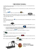
Page 24: ... using the WORKOUT INTENSITY LEVEL TIMER timer buttons until the desired workout time appears in the TIMER WINDOW If you hold either of the buttons down the time scrolls quickly If you wish to include warm up and or cool down to your workout press the Cool Down Workout Warm Up button until the indicator light next to the desired mode is illuminated You will notice that your workout time will autom...

Page 25: ...es Total workout time can be set from 15 to 55 minutes in 10 minute increments this includes a warm up cool down TIP Warm up and cool down periods are automatically added to all the Variable Intensity Workouts If you wish to remove the warm up and or cool down phases press the warm up cool down button Cool Down Workout Warm Up until the corresponding indicator light is no longer illuminated Step F...

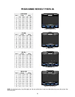
Page 26: ...3 0 4 6 2 5 6 5 5 3 6 5 2 3 0 7 0 6 4 2 5 8 3 5 7 5 7 4 8 6 4 4 0 8 0 8 5 4 7 0 4 5 8 5 9 6 0 7 6 5 0 9 0 STAMINA Level Speed Incline Min Max Min Max 1 1 4 2 6 0 0 6 0 2 2 0 3 2 0 0 6 0 3 2 6 3 8 0 0 6 0 4 3 2 4 4 0 0 6 0 5 3 8 5 0 0 0 6 0 6 4 4 5 6 0 0 6 0 7 5 0 6 2 0 0 6 0 8 5 6 6 8 0 0 6 0 9 6 2 7 4 0 0 6 0 INTERVAL Level Speed Incline Min Max Min Max 1 1 6 2 8 0 0 6 0 2 2 2 3 4 0 0 6 0 3 2 8 4...

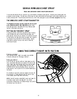
Page 27: ...results the strap should be worn against skin Moisture is necessary for the transmitter to function properly Usually perspiration is sufficient but you may need to moisten the electrodes with water USING THE CONTACT HEART RATE FEATURE Prior to your workout Insert the magnetic key adjust your weight press ENTER Follow the instructions for During your workout During your workout Grab on to the front...

Page 28: ...rogram For Total Well Being The main idea of this system is that in order to stay in good shape and move toward a goal of total well being a person must earn a certain number of points each week by doing a certain amount of aerobic exercise His research has determined that a man should work up to a minimum of 32 points per week and a woman should work up to a minimum of 27 points per week The numb...

Page 29: ... up and or cool down by pressing the Cool Down Workout Warm Up button Step Five Press the Calories Distance Aerobic Pts button until the Aerobic Points indicator is illuminated Step Six Enter speed You will begin to see the number of Aerobic points you will earn in the RESULTS DISPLAY as you increase the speed Step Seven Enter Incline You will begin to see the number of Aerobic points you will ear...

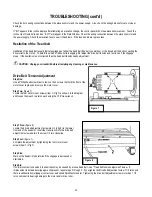
Page 30: ...readmill Deck and Tread Belt Cleaning The running belt on your PaceMaster rides on a low friction deck Performance will be compromised if any foreign matter comes between the tread belt and the deck For this reason extra care must be used in keeping the tread belt clean Use a soft damp cloth to remove dust dirt and foreign matter from the area along side of the belt Do not clean the tread belt by ...

Page 31: ...6 Hex wrench turn the left hand adjustment bolt 1 a quarter turn clockwise and the right hand adjustment bolt 2 a quarter turn counter clockwise If the belt is drifting to the right using a 3 16 Hex wrench turn the right hand adjustment bolt 2 a quarter turn clockwise and the left hand adjustment bolt 1 a quarter turn counter clockwise Step Two Plug the treadmill in to the outlet and run the tread...

Page 32: ...rmine the precise reason for a problem If the onboard computer detects a problem an error code will be displayed If an error code appears during operation of your treadmill do the following Make a note of the error code number see next page for example Obtain your serial number located on the front of the treadmill approximately 10 12 inches to the left of the power cord Write down which mode of o...

Page 33: ...iring connections optical sensor and wiring harness and all wiring for cuts or damage See step 2 page 8 Error Code 307 Indicates that there was no speed sensor signal at start up Check the speed sensor connection and wiring Error Code 425 After start is pressed the tread belt does not move and then Err 425 appears To reset this error code you must unplug the treadmill from the wall outlet for 10 s...

Page 34: ...intenance Drive Belt Tension Adjustment Step One Use a Phillips head screwdriver to remove the 2 screws that hold the front of the motor cover in place and remove the motor cover Step Two figure 7 Locate the four motor mount screws item 1 in fig 7 as shown in the diagram and loosen them each two turns each using the 3 16 Hex wrench Step Three figure 8 Locate the drive belt adjustment screw item 2 ...

Page 35: ...he left and right tread belt adjustment screws 1 2 turn clockwise Step Three Walk on the treadmill to see if the adjustment you made decreased the slippage Step Four If a significant decrease in slippage was observed go to step 2 If you tighten the tread belt 1 1 2 turns per side and slippage is still present do not continue to adjust the tread belt tension Contact your authorized PaceMaster deale...

Page 36: ... the total hours and miles on my treadmill A Insert the magnetic safety key when the set weight indicator begins to flash press and hold the WORKOUT INTENSITY LEVEL button the total time and mileage will appear in their respective windows and the power supply software version will appear in the INCLINE Q Can I eliminate warm up and or cool down from a Variable Intensity Workout A Yes If you wish t...

Page 37: ...ted Deck Custom designed medium density fiberboard Rollers 2 5 OD precision machined steel with permanently lubricated sealed bearings Shock Absorption System Tri Flex Low Impact Cushioning System Speed Range 0 5 to 12 0 mph adjustable in 0 1 mph increments Elevation Range 0 to 15 grade adjustable in 0 5 increments Workout Programs Conditioning Stamina Interval Weight Loss and Manual Weight Limit ...

Reviews: