background image

HANDPIECE SETUP

Use the following procedures to set up your handpiece.

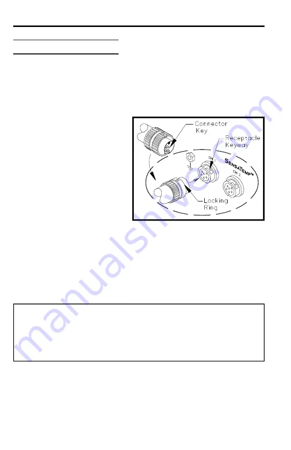
Power Receptacle Connection

Connect the handpiece power
cable plug to one of the power
receptacles on your PACE power
source.  PACE recommends that
air handpieces utilize the power
receptacles closest to the 

AUTO

SNAP-VAC

 (or 

SNAP-VAC

) and

Controllable  

PRESSURE 

 Ports

to minimize cord tangles.  Refer
to the Operation & Maintenance
Manual included with your power
source for details.

Air Hose Connection

There are two methods of attaching the air hose from the PACE power source
to the TP-65.  Select the method which best suits your needs.  The Quick
Connect Method is best suited for SensaTemp handpiece configurations where
multiple air handpieces may be in use.  The Traditional Method is best suited
for single air handpiece configurations.

CAUTION

Regardless of connection method, ensure that only one air hose is
connected to the power source 

AUTO SNAP-VAC 

(or 

SNAP-VAC

) or

Controllable 

PRESSURE

 Port at one time.  Attachment to both ports

simultaneously will cause a deterioration of performance.

Artisan Technology Group - Quality Instrumentation ... Guaranteed | (888) 88-SOURCE | www.artisantg.com

Summary of Contents for TP-65

Page 1: ...l service in house repair center WE BUY USED EQUIPMENT Sell your excess underutilized and idle used equipment We also offer credit for buy backs and trade ins www artisantg com WeBuyEquipment REMOTE INSPECTION Remotely inspect equipment before purchasing with our interactive website at www instraview com LOOKING FOR MORE INFORMATION Visit us on the web at www artisantg com for more information on ...

Page 2: ...OPERATION MAINTENANCE INSTRUCTIONS TP 65 TP 65 THERMOPIK HANDPIECE Artisan Technology Group Quality Instrumentation Guaranteed 888 88 SOURCE www artisantg com ...

Page 3: ...ly be used to identify genuine PACE products or services Arm Evac Mini Wave PACE SensaTemp Snap Vac Sodrtek Sodr X Tractor ThermoFlo ThermoJet ThermoTweez ToolNet VisiFilter Since1958 PACEIncorporatedhasprovidedadvanced technology training in all aspects of hand soldering rework and repair For any questions regarding the following instructions contact your local authorized PACE dealer or contact P...

Page 4: ...for initial use in most applications You should determine the lowest possible removal temperature to work with on your board and component types A low temperature extends tip life NOTE Always use this handpiece in a well ventilated area to avoid the inhalation of fumes created by the heating of solder flux Remember that the ThermoPik is a component removal tool and is not intended for installation...

Page 5: ...are two methods of attaching the air hose from the PACE power source to the TP 65 Select the method which best suits your needs The Quick Connect Method is best suited for SensaTemp handpiece configurations where multiple air handpieces may be in use The Traditional Method is best suited for single air handpiece configurations CAUTION Regardless of connection method ensure that only one air hose i...

Page 6: ... side of the VisiFilter insert a female quick connect hose mount fitting P N 1259 0086 b To the free end of the 2 5cm 1 inch air hose connected to the FLOW OUT side of the VisiFilter insert a male quick connect hose mount fitting P N 1259 0087 c Insert the end of the male quick connect hose mount fitting on VisiFilter FLOW OUT side into the power source AUTO SNAP VAC or SNAP VAC Port 5 Connect the...

Page 7: ...isting of available tips Contact your local authorized PACE dealer for the latest Tips Accessories Catalogue which details all availabletips TIP INSTALLATION 1 Carefully remove any installed vacuum cup from the TP 65 using the tip tool and set aside 2 Select the proper tip for your application Refer to Table I 3 Insert the tip shaft fully into the heater bore 4 Using the tip tool tighten the heate...

Page 8: ...0 62 PQFP 84 Tip 18 3 x 18 3mm 1121 0324 0 72 x 0 72 APPLICATION PQFP 100 Tip 20 8 x 20 8mm 1121 0325 0 82 x 0 82 PQFP 132 Tip 25 9 x 25 9mm 1121 0326 1 02 x 1 02 PQFP 144 29 2 x 29 2mm 1121 0456 1 15 x 1 15 PQFP 208 30 0 x 30 0mm 1121 0544 1 18 x 1 18 PQFP 160 Tip PQFP 208 Tip 31 0 x 31 0mm 1121 0351 1 22 x 1 22 PQFP 196 Tip 36 3 x 36 3mm 1121 0483 1 43 x 1 43 NOTE All dimensions are nominal insi...

Page 9: ...rs on the vacuum pick is 74mm 2 9inches from the end of the pick rod to the front edge of the first collar This setting is correct for removal of most components 1 Using the tip tool remove the vacuum cup and set aside 2 Remove the handpiece rear seal and compression spring and set aside 3 Slide out the vacuum tube assembly and locate the two Collars 4 Adjust the Collars in the following manner a ...

Page 10: ...A B 74mm 2 9 Artisan Technology Group Quality Instrumentation Guaranteed 888 88 SOURCE www artisantg com ...

Page 11: ...ypes Refer to the Tip Temperature Selection System Chart P N 5050 0251 booklet for your particular handpiece tip combination For all Dial Display systems the booklet will indicate the correct Dial Display setting for the True Tip Temperature desired On systems incorporating a Digital Readout set the desired operating temperature and Tip Offset Constant for the TP 65 handpiece tipcombination PCB CO...

Page 12: ...ls e g ceramic polyamide etc or those with an exceptionally heavy ground or power planes may require the use of a preheating system such as the PACE Heat Wave 4 In order to maximize heat transfer from the handpiece tip to PQFP component lead land connections PACE recommends adding bridgefill solder wrap or flux to maximize heat transfer across all connections Artisan Technology Group Quality Instr...

Page 13: ...perature of 315 C 600 F and adjust as necessary 3 Enter Tip Offset Constant for the selected tip 4 Install QFP Removal Tip into ThermoPik using TipTool 5 Install vacuum cup onto vacuum pick tube using Tip Tool 6 Remove old solder from tip with sponge Tin inside and bottom edges of tip with solder 7 Lowertipovercomponent contacting ALL leads with tip see 8 Confirm solder melt of ALL joints apply va...

Page 14: ...he PCB and to prepare the lands for accepting a new part Refer to one of the SX 80Sodr X Tractormanualsforsuggestedsolderremovaltechniques SPECIAL APPLICATIONS If you require assistance in the use of this handpiece or require assistance with a special application contact PACE Product Management at Telephone 301 490 9860 Fax 301 604 8782 Artisan Technology Group Quality Instrumentation Guaranteed 8...

Page 15: ...edure column NOTE The handpiece Heater Assembly must be at room temperature 22 C or 72 F before performing Heater Assembly Checkout Procedures Table II Heater Assembly Checkout Procedures SYMPTOM CHECKOUT PROCEDURE CAUSE SOLUTION No heat Check resistance Pin 2 to Pin 5 Resistance should be 10 ohms If not Open Heater Replace Heater Assembly Check resistance Pin 3 to Pin 6 If circuit reads open Open...

Page 16: ...sembly 4010 0101 P1 Tip and Vacuum Cup Tool 1100 0239 Heater Set Screw 1348 0547 P10 Vacuum Cups 4 4 mm 0 175 O D 1121 0382 P5 7 6mm 0 300 O D 1121 0383 P5 12 7mm 0 500 O D 1121 0384 P5 Kit with 3 cups 1 each size 6993 0153 P1 SX Tip Tool Stand 6019 0044 P1 Tip Redi Rak 6021 0007 P1 Tip Maintenance Station 6993 0138 Artisan Technology Group Quality Instrumentation Guaranteed 888 88 SOURCE www arti...

Page 17: ...8 535 PACE 7223 Fax 301 498 3252 PACEEUROPE SherbourneHouse SherbourneDrive Tilbrook Milton Keynes MK78HX UnitedKingdm Tel 44 1908 277666 Fax 44 1908 277777 www paceworldwide com Artisan Technology Group Quality Instrumentation Guaranteed 888 88 SOURCE www artisantg com ...

Page 18: ...l service in house repair center WE BUY USED EQUIPMENT Sell your excess underutilized and idle used equipment We also offer credit for buy backs and trade ins www artisantg com WeBuyEquipment REMOTE INSPECTION Remotely inspect equipment before purchasing with our interactive website at www instraview com LOOKING FOR MORE INFORMATION Visit us on the web at www artisantg com for more information on ...

Reviews: