6-6
08/12
Section 6
Body Mounting
MOUNTING HOLES
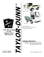
When installing the lower bracket on frame rails the mounting holes in the chassis frame bracket and frame rail must com
-
ply with the general spacing and location guidelines illustrated in Figure 6–10. The hole diameter should not exceed the
bolt diameter by more than .060 inches (1.5 mm).
4 HOLES
.5 IN. DIA.
(12.7mm)
5.5
(140mm)
2.0
(50mm)
5.63
(143mm)
5.5
(140mm)
2.0
(50mm)
5.63
(143mm)
11.0
(279mm)
6 HOLES
.5 IN. DIA.
(12.7mm)
FIGURE 6-10.
Crossmember-Gusset Hole Pattern Requirements. [inch (mm)]
Frame Drilling
When mounting a body to the chassis, DO NOT drill holes in the
upper or lower flange of the frame rail. If the frame rail flanges are
modified or damaged, the rail could fail prematurely and cause an
accident. Mount the body using body mounting brackets or U–bolts.
Use care when drilling the frame web so the wires and air lines routed inside the rail are
not damaged, Failure to do so could cause an inoperable electrical or air system circuit.
Do not drill closely spaced holes in the frame rail. Hole centers of two adjacent holes
should be spaced no less than twice the diameter of the largest hole. closer spacing could
induce a failure between the holes.
WARNING:
CAUTION:
WARNING:
143 mm
(5.63”)
62 mm
(2.4”)
140 mm
(5.5”)
4 Holes
13.2 mm diameter
(0.5”)
6 Holes
13.2 mm diameter
(0.5”)
280 mm
(11”)
140 mm
(5.5”)
143 mm
(5.63”)
62 mm
(2.4”)
Summary of Contents for Kenworth T800 2012
Page 1: ...Kenworth Heavy Duty Body Builder Manual 2012...
Page 2: ...This page intentionally left blank...
Page 3: ...Kenworth Heavy Duty Body Builder Manual...
Page 10: ...This page intentionally left blank...
Page 12: ...This page intentionally left blank...
Page 61: ...3 41 Section 3 Dimensions 08 12 Allison Transmission...
Page 62: ...3 42 Section 3 Dimensions 08 12 This page intentionally left blank...
Page 86: ...08 12 4 24 Section 4 Exhaust Aftertreatment This page intentionally left blank...
Page 212: ...6 10 08 12 Section 6 Body Mounting This page intentionally left blank...
Page 220: ...7 8 08 12 Section 7 Frame Modifications This page intentionally left blank...
Page 242: ...8 22 08 12 Section 8 Electrical Figure 8 15 Specialty Switches...
Page 244: ...8 24 08 12 Section 8 Electrical FIGURE 8 17 Spare Relay Harnesses...
Page 266: ...8 46 08 12 Section 8 Electrical This page intentionally left blank...
Page 275: ...A 5 08 12 Appendix A Vehicle Identification This page intentionally left blank...