23
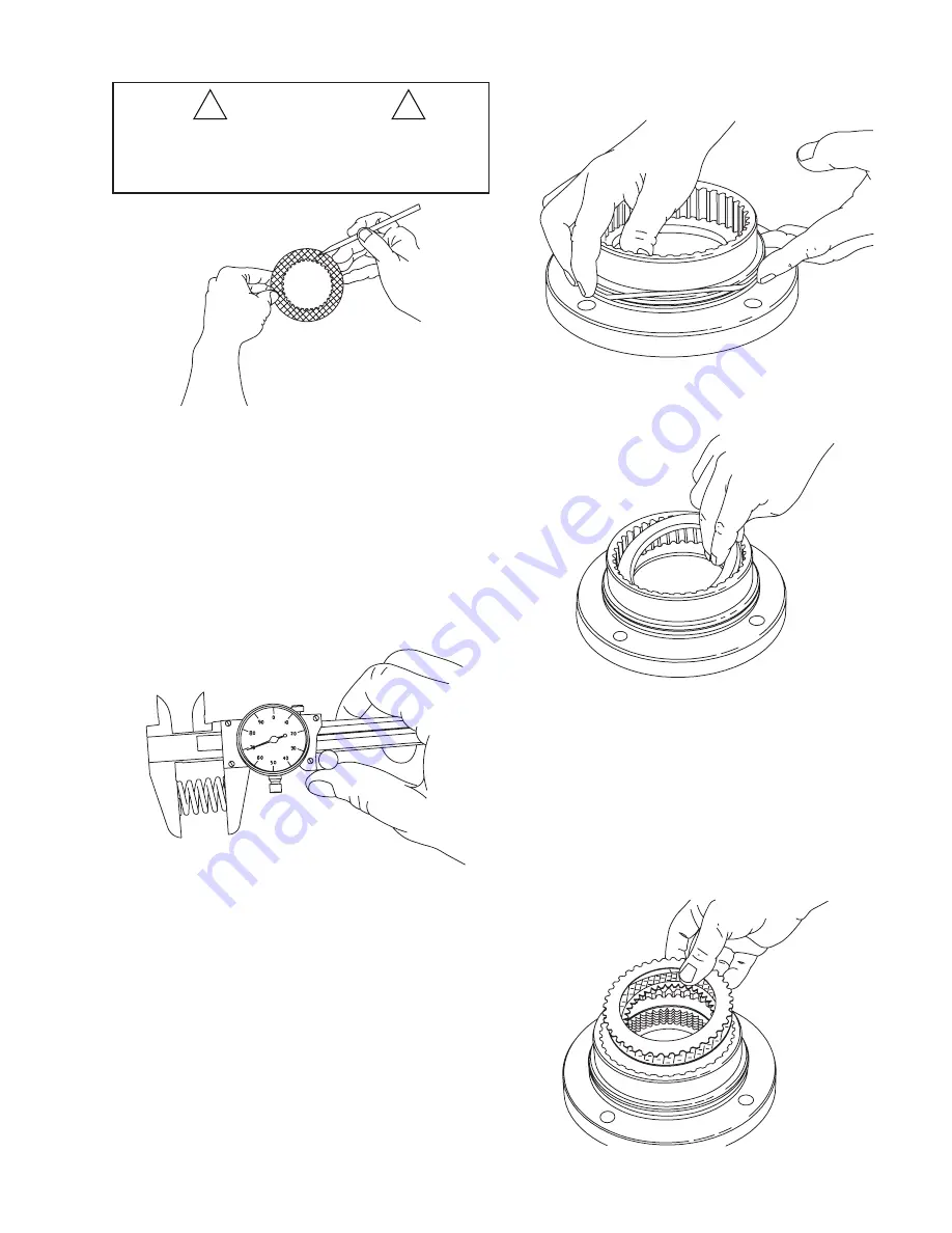
4. Place steel brake disc on
fl
at surface and check for distor-
tion with a straight edge. Check surface for signs of mate-
rial transfer or heat. Replace steel disc if splines are worn
to a point, disc is distorted or heat discolored.
5. Check brake spring free length; minimum free length is 1
3/16 in. (30.2 mm). Check springs for any sign of crack-
ing or failure. If a brake spring must be replaced for any
reason, then ALL brake springs must be replaced.
ASSEMBLY
1. Begin assembly by placing motor support on workbench
with motor mounting surface down. Install new O-ring
and backup ring as shown.
2. Install a brake spacer into the motor support. (NOT RE-
QUIRED WITH LOBED DISCS.)
3. Insert
fi
rst, a steel brake disc against the spacer followed
by a friction brake disc then alternate steel and friction
discs until seven (7) friction and eight (8) steel discs have
been installed. Finish with a steel brake disc on top.
NOTE:
It is a good practice to pre-lubricate the discs
in hydraulic oil prior to assembly.
4. Install the remaining brake spacer on top of the last steel
brake disc. (
Th
is is the only spacer used with lobed discs.)
5. To check brake stack height, place pressure plate on top
of brake spacer. Hold pressure plate down
fi
rmly by hand
and measure clearance in three places between motor
support and pressure plate. Average gap must measure
between .153 in. (4 mm) maximum and .080 in. (2 mm)
minimum. If the gap exceeds the maximum limit, there
are too many brake discs in stack-up or the discs are dis-
torted. If the gap is less than the minimum, there are too
few discs in stack-up or the discs are worn out. When
stack height is correct, remove pressure plate and contin-
ue assembly.
CAUTION
!
!
Failure to replace brake springs as a set may result in un-
even brake application pressure and repeated brake spring
failure.


