


Reverse Camera Input and Navigation Unlock
Interface for Chrysler / Dodge / Jeep / RAM Vehicles
BCI-CH41
(v2)
© 2018 AAMP Global. All rights reserved. PAC is a Power Brand of AAMP Global.
PAC-audio.com
Pacific Accessory Corporation
Rev: V3
Date: 040918
Page 3
Common Use Examples w/Setup
Adding Reverse Camera Only
•
DIP switch 1
= ON
•
DIP switch 2
= OFF
•
DIP switch 3
= OFF
•
DIP switch 4
= User Preference
•
No additional programming needed as Programmable Output 1
(10A) is set to “Accessory” by default (use to power cameras)
Adding Reverse Camera and Navigation Unlock
•
DIP switch 1
= ON
•
DIP switch 2
= OFF
•
DIP switch 3
= ON
•
DIP switch 4
= User Preference
•
No additional programming needed as Programmable Output 1
(10A) is set to “Accessory” by default (use to power camera)
Adding Reverse Camera and Rear Media
•
DIP switch 1
= ON
•
DIP switch 2
= ON
•
DIP switch 3
= User Preference
•
DIP switch 4
= User Preference
•
No additional programming needed as Programmable Output 1
(10A) is set to accessory by default (use to power cameras and
video source)
Adding Reverse Camera and a Bed Camera using the AVS21
(sold separately)
•
DIP switch 1
= ON
•
DIP switch 2
= OFF
•
DIP switch 3
= OFF
•
DIP switch 4
= User Preference
•
PC Settings
•
Blind Spot Camera
= OFF.
•
Front Camera
= OFF
•
Programmable Output 1 (10A)
= Any Camera Active or
Accessory (use to power cameras)
•
Programmable Output 2 (1A)
= Forced Reverse Camera
(use to trigger AVS21 when the forced reverse camera
feature is triggered via the SWC or the on-demand switch)
•
Programmable Output 3 (1A)
= OFF
Adding Blind Spot Cameras using the VS41 (sold separately)
•
DIP switch 1
= ON if adding rev cam; OFF if already equipped
•
DIP switch 2
= OFF
•
DIP switch 3
= User Preference
•
DIP switch 4
= User Preference
•
PC Settings
•
Blind Spot Camera
= User Preference, can’t be OFF
•
Front Camera
= Off
•
Programmable Output 1 (10A)
= Any Camera Active or
Accessory (use to power cameras)
•
Programmable Output 2
= OFF
•
Programmable Output 3
= OFF
Adding Blind Spot Cameras and a Front Camera using the VS41
(sold separately)
•
DIP switch 1
= ON if adding reverse camera; OFF if already
equipped
•
DIP switch 2
= OFF
•
DIP switch 3
= User Preference
•
DIP switch 4
= User Preference
•
PC Settings
•
Blind Spot Camera
= User Preference, can’t be OFF.
•
Front Camera
= User Preference, can’t be OFF.
•
Programmable Output 1 (10A)
= Any Camera Active or
Accessory (use to power cameras)
•
Programmable Output 2 (1A)
= OFF
•
Programmable Output 3 (1A)
= OFF
Adding Reverse Camera, Blind Spot Cameras, and a Front
Camera using the VS41 (sold separately), a bed camera using
the AVS21 (sold separately), Navigation Unlock, and Rear Media
•
DIP switch 1
= ON
•
DIP switch 2
= ON
•
DIP switch 3
= ON
•
DIP switch 4
= User Preference
•
PC Settings
•
Blind Spot Camera =
User Preference, can’t be OFF.
•
Front Camera = User Preference, can’t be OFF.
•
Programmable Output 1 (10A) = Accessory (use to power
cameras and video source)
•
Programmable Output 2 (1A) = Forced Reverse Camera
(use to trigger AVS21 when the forced reverse camera
feature is triggered via the SWC or the on-demand switch)
•
Programmable Output 3 (1A) = OFF
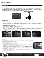
Reverse Camera
Rear Media
Navigation Unlock
Feature Settings Menu
1
2
3
4
Set DIP switches to the ON position to activate the corresponding features.
Set DIP switches to the OFF position for any features that are not desired.