


Reverse Camera Input and Navigation Unlock
Interface for Chrysler / Dodge / Jeep / RAM Vehicles
BCI-CH41
(v2)
© 2018 AAMP Global. All rights reserved. PAC is a Power Brand of AAMP Global.
PAC-audio.com
Pacific Accessory Corporation
Rev: V3
Date: 040918
Page 2
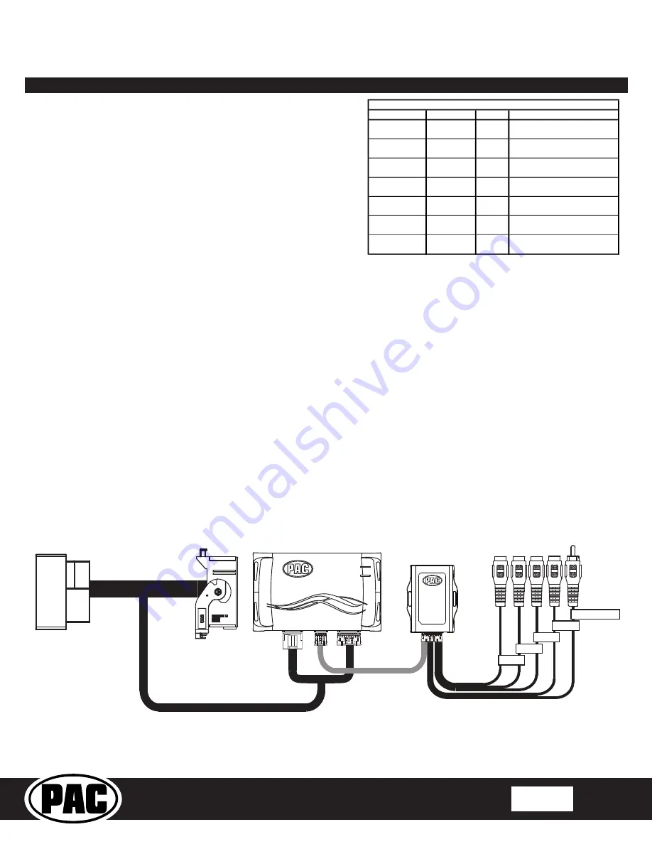
Connecting a VS41 (sold separately)
If you are adding a front camera and two blind spot cameras, or any combination of the three, to the factory radio, a VS41 (sold separately)
can be used in conjunction with the BCI. Follow the example below to make all inputs work accordingly through the one camera input on
the factory radio. Connect the 10-pin harness from the VS41 harness into the Expansion Port on the BCI-CH41. Do not manually wire the
trigger wires, or power and ground leads, when using the Expansion Port connector. When the appropriate CAN-Bus signals are detected (ie.
reverse, or turn signal) the corresponding camera input will be automatically selected, and it’s video feed will be routed to the factory radio
display.
The behaviors of the cameras and output wires can be configured using the BCI app. Please see page 6 for full details on using the BCI app.
Righ
t C
amer
a
Lef
t C
amer
a
Fr
on
t C
amer
a
Rev
erse C
amer
a
VIDEO OUTPUT
Video 4
Video 3
Video 2
Video 1
BCI-CH41-HAR
BCI-CH41
VS41
(Sold Separately)
To Radio
To Vehicle
Harness
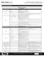
Installation Steps (cont.)
Wire
Color
Function
Note
Prog. Output 1
Blue
12v+
10 Amp positive output when user
programmed feature is activated
Prog. Output 2
Blue / White
12v+
1 Amp positive output when user
programmed feature is activated
Prog. Output 3
Blue / Red
12v+
1 Amp positive output when user
programmed feature is activated
Left Camera
Red
12v+
1 Amp positive output when left
blind spot camera is activated
Left Camera
Black
Ground
Negative output when left blind
spot camera is activated
Right Camera
Red
12v+
1 Amp positive output when right
blind spot camera is activated
Right Camera
Black
Ground
Negative output when left blind
spot camera is activated
Trigger Wires
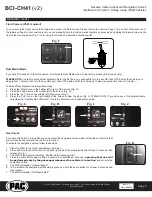
5. Connect the aftermarket reverse camera’s video output to the female
camera input located on the radio side of the BCI-CH41 harness. If you
are also adding blind spot and / or a front camera, the VS41 must be
used (sold separately). See below for VS41 wiring. You can also use any
universal video switcher and utilize the programmable outputs to trigger
as necessary.
6.
Connect the trigger wire(s) as needed. Please see chart for trigger wire
colors and functions.
7. If you wish to use the on-demand activation feature, run and mount the
toggle switch on the BCI-CH41 harness to the desired location. PLEASE
NOTE: If you are not adding a front camera, the on-demand switch will
only trigger the reverse camera.
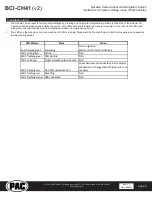
8.
If you are adding an additional A/V input:
Connect the A/V outputs from
the source to the Rear Media inputs on the radio side of the BCI-CH41
harness. If you have more than one source, the AVS21 or any other
universal video switcher must be used (sold separately).
9.
Connect the male connector on the BCI-CH41 harness to the factory radio.
10.
Turn the ignition to the on position.
11.
Plug the 4-pin and 20-pin plugs on the BCI-CH41 harness into interface connector 1 and 2.
12.
Both LEDs will blink green while the module is initializing. Once initialized, LED 1 will turn solid red and LED 2 will begin blinking green. If
LED 2 blinks red, there is a problem with the data connection to the factory radio. In this case please refer to the troubleshooting section
on page 8.
13. Turn the vehicle off, shut the doors and lock the vehicle with the factory keyfob. Wait 10 minutes. After 10 minutes, turn vehicle back on and
test BCI operation (see operation section on page 4). Sometimes it may take more than one sleep cycle to engage all features, especially
the performance page feature.