9 |
P a g e
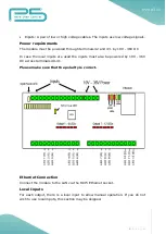
Connect dry contacts (pushbuttons, momentary switches, relay contacts, etc.)
across the appropriate input terminals and the input common terminal.
WARNING! Avoid supplying voltage on these terminals!
All input ports are galvanically isolated to protect the unit against unwanted effects
of ground loops, overvoltage or misconnections.
The galvanic isolation is only effective when a separate power supply is used for
powering the inputs on terminals 40, 41.
If you choose not to use the extra protection the isolated inputs offer, you can use
the same power to supply both the main circuit and the inputs. In that case simply
connect terminal 41 to terminal 43 and terminal 40 to terminal 42.
Three-way switches can be implemented by simply connecting multiple
momentary switches in parallel.
Status LED Indicators
In order to make installation and debugging easier, communication and channel
status are displayed via LEDs.
Input status LEDs
Each input has a dedicated status LED that illuminates solid green when the
corresponding input is activated.
MCU live LED
When on, indicates that the FNIP-12xPWM unit is running.
Input power LED
When on, indicates that the input power is present.
Output status LEDs
Each output has a dedicated status LED that illuminates solid red when the
corresponding output is activated.
Summary of Contents for FNIP-12xPWM
Page 3: ...3 P a g e ...
Page 13: ...13 P a g e Figure 6 Network configuration page ...


