7 |
P a g e
Wiring
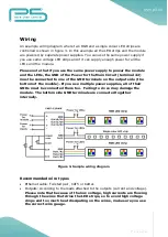
An example wiring diagram where two RGB and a single colour LED strips are
controlled is shown in figure 3. In this example all the LED strips and the module
are powered by separate power supplies. You can use the same power supply if
you use same voltage LED strips and if it can supply enough power for all the
LEDs and the module.
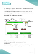
Please note that if you use the same power supply to power the module
and the LEDs, the GND of the Power for the Main Circuit (terminal 42)
must be connected to one of the GND terminals on the output side (the
bottom of the module). If you use multiple power supplies, all of their
GNDs must be connected there too. Failing to do so may damage the
module. The bottom side GND terminals are connected together
internally.
Figure 3. Sample wiring diagram
Recommended wire types
Ethernet cable: Twisted pair, CAT5 or better.
Outputs: According to the loads attached to the outputs (current and voltage).
Please note that because of the low voltage, high currents are flowing
through the wires that drive the LED strips, so to avoid high voltage
drops and too much heat dissipating on the wires, make sure you use
the correct wire gauge.
Summary of Contents for FNIP-12xPWM
Page 3: ...3 P a g e ...
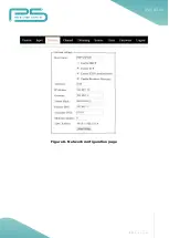
Page 13: ...13 P a g e Figure 6 Network configuration page ...


