8 |
P a g e
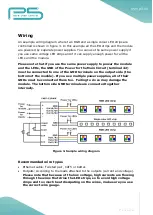
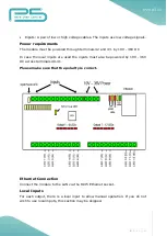
Inputs: A pair of low or high voltage cables. The inputs use low voltage signals.
Power requirements
The module must be powered through terminals 42 and 43. by 10V - 36V DC
In case the local inputs are used the inputs must also be powered by 10V - 36V
DC across terminals 40-41.
Please make sure that the polarity is correct.
Ethernet Connection
Connect the module to the LAN via the RJ45 Ethernet socket.
Local Inputs
For each output, there is a local input to allow manual operation. If you do not
wish to use local inputs, this section may be skipped.
Summary of Contents for FNIP-12xPWM
Page 3: ...3 P a g e ...
Page 13: ...13 P a g e Figure 6 Network configuration page ...


