background image


12 

and connect the reference wire clamp to the ground wire connector of the 

probe compensator, and then press the 

Auto

 key on the front panel. 

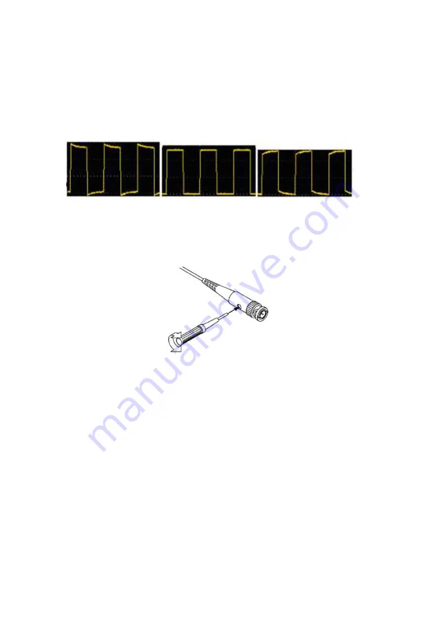
2. Check the displayed waveform and adjust the probe until the compensation 

is correct. See 

Figure 3-4

 and 

Figure 3-5

. 


Overcompensation      Correct compensation    Under-compensation 


Figure 3-4: Display Waveform of Probe Compensation 

3. Repeat the steps if necessary. 


Figure 3-5: Probe Adjustment 

Probe Attenuation Coefficient Setting 

The probe has a variety of attenuation coefficients, which will affect the vertical 

position factor of the oscilloscope. 

To change (check) the set value of probe attenuation coefficient in the 

oscilloscope menu, please follow the steps below: 

(1) Press the 

CH1/CH2

 key to switch the channel to be used. 

(2) Press the 

F3

 to select the desired attenuation coefficient. This setting is 

valid until it is changed again. 


Summary of Contents for DSO-2072H

Page 1: ...DSO 2072H Handheld Oscilloscope Quick Guide ...

Page 2: ... Interface of the Oscilloscope 9 Functional Check 10 Probe Compensation 11 Probe Attenuation Coefficient Setting 12 Safe Use of Probe 13 4 How to Use the Multimeter 14 About This Chapter 14 Instrument Interface 14 5 How to Use the Waveform Generator optional 16 Connect the output 16 Set the waveform 16 6 Troubleshooting 17 7 Appendix 18 Appendix A List of Accessories 18 Appendix B Maintenance and ...

Page 3: ...may appear on this product Danger Indicates an immediate hazard or injury possibility Warning Indicates a possible hazard or injury Caution Indicates potential damage to the instrument or other property Safety Symbols Symbols on the product The following symbol may appear on the product Hazardous Voltage Refer to Manual Protective Earth Terminal Chassis Ground Test Ground Safety Requirements Pleas...

Page 4: ...ng Note that the channel should use a common reference when measuring otherwise it may cause a short circuit due to the ground wire connection of the oscilloscope probe Schematic diagram of the internal ground wire connection of the oscilloscope Ground Clip Signal Input Oscilloscope AC Adapter Electrical Outlet Probe USB Cable When the oscilloscope is AC powered by adapter or connected with AC pow...

Page 5: ...nstrument Pay special attention when using 1 1 test wires because the probe voltage will be directly transmitted to the oscilloscope Do not touch the bare metal BNC or banana plug Do not insert metal objects into the connector Use the oscilloscope only in the specified way The voltage rating mentioned in the warning information is the limited value of working voltage They represent V ac rms 50 60 ...

Page 6: ...ous damage do not throw it away first till the complete device and its accessories succeed in the electrical and mechanical property tests 2 Check the Accessories The supplied accessories have been already described in the Appendix A List of Accessories of this Manual You can check whether there is any loss of accessories with reference to this description If it is found that there is any accessor...

Page 7: ... V DC 2 A internal rechargeable batteries inserted Note Use the supplied USB Cᵀᴹ to USB A cable Any replacement cable should be of the correct type and specification Refer to section General Technical Specifications for further information The Structure of the Oscilloscope Front Panel and Keys The front panel and keys of the oscilloscope are shown in Figure 3 1 ...

Page 8: ...y to select the corresponding menu item 5 After pressing the HOR key through the key you can change the horizontal time base setting and observe the change of the state information caused by it it can also be found that the horizontal time base display corresponding to the status bar has changed correspondingly the horizontal displacement of the signal in the waveform window can be adjusted by pre...

Page 9: ...d right movements of waveform the voltage position changing and the movements of time cursor in the oscilloscope 9 Automatic setting key oscilloscope or automatic range key multimeter 10 Stop run key oscilloscope or value hold key multimeter or turn on off the signal output waveform generator optional 11 Input end of the multimeter 12 Trigger menu key oscilloscope or relative value key multimeter ...

Page 10: ...8 Side Panel 1 2 3 Description 1 Probe compensation 3 3V 1kHz square wave signal output 2 Charging or USB communication interface 3 Bracket ...

Page 11: ...g collected Ready All pre trigger data have been obtained and the oscilloscope is ready Scan Scan mode Continuously collect and display waveform data Stop Stop collecting waveform data 2 Run stop 3 Time base display 4 The pointer indicates the trigger horizontal position 5 The pointer indicates the trigger position within the current storage depth 6 Indicating the value of the current trigger hori...

Page 12: ...ding reference point zero position of the waveform displayed in CH2 channel If there is no pointer indicating the channel it means that the channel is not open 16 The pointer indicates the grounding reference point zero position of the waveform displayed in CH1 channel If there is no pointer indicating the channel it means that the channel is not open 17 Waveform display area Functional Check Maki...

Page 13: ... square wave display 1kHz 3 3Vpp can be seen as shown in Figure 3 3 Figure 3 3 Automatic Setting Repeat steps 2 and 3 on the CH2 channel Probe Compensation When connecting the probe to any input channel for the first time make this adjustment to match the probe with the input channel The probe without compensation or deviation compensation will lead to measurement error To adjust the probe compens...

Page 14: ...y Waveform of Probe Compensation 3 Repeat the steps if necessary Figure 3 5 Probe Adjustment Probe Attenuation Coefficient Setting The probe has a variety of attenuation coefficients which will affect the vertical position factor of the oscilloscope To change check the set value of probe attenuation coefficient in the oscilloscope menu please follow the steps below 1 Press the CH1 CH2 key to switc...

Page 15: ...e setting value of the probe switch is 1X and 10X See Figure 3 6 Figure 3 6 Probe Attenuation Switch Note When the attenuation switch is set to 1X the probe limits the bandwidth of the oscilloscope to 5 MHz To use the full bandwidth of the oscilloscope be sure to set the switch to 10X Safe Use of Probe The safety ring surrounding the probe body provides a barrier to protect the fingers from electr...

Page 16: ...making any measurements connect the probe to the instrument and connect the ground terminal to the ground 4 How to Use the Multimeter About This Chapter This chapter introduces the multimeter function of the oscilloscope step by step and provides some basic examples of basic operations and how to use the menu Instrument Interface The multimeter uses four 4 mm safety banana plug input ends A mA COM...

Page 17: ...nge 4 Indicating that there is a USB cable inserted 5 Battery power indication 6 Hold can keep the current reading on the display 7 Measurement value and unit 8 Display of switching resistance buzzer diode and capacitance measurement function 9 The selected range V or mV in voltage measurement the selected current range A or mA in current measurement 10 To choose AC or DC voltage measurement 11 To...

Page 18: ...o switch Connect the BNC cable to the port marked GEN Out in the top of the oscilloscope Generator Output Ports To observe the output of the waveform generator connect the other end of the BNC cable to the signal input connector of the oscilloscope Set the waveform 1 Press the Mode button to switch the instrument interface to the waveform generator function interface 2 Press F1 to select the desir...

Page 19: ... to the multimeter the measurement type is displayed as E It may be that the measurement type was not selected At this time press F4 the measurement type should display the corresponding measurement type If E is still displayed restart the oscilloscope 4 In the oscilloscope state the measured voltage amplitude value is 10 times larger or smaller than the actual value Check whether the channel atte...

Page 20: ...set in the acquisition mode or the duration is set longer in the display settings It is normal 7 Appendix Appendix A List of Accessories Oscilloscope USB Cᵀᴹ to USB A data charging cable Probe Probe adjust BNC to alligator clip cable Carrying bag Multimeter test leads red black CD ROM software manual safety sheet quick guide Quick guide Safety sheet Appendix B Maintenance and Cleaning General main...

Page 21: ...personal injury caused by moisture Battery Charging During the long term storage of the device the battery may be too low due to the self discharge of the lithium battery and the device cannot be turned on This is a normal phenomenon Pre charge the device for 0 5 to 1 hour depending on the storage time before turning it on In addition if the device is not used for a long time it is recommended to ...

Page 22: ...e Connect the oscilloscope to a computer or other equipment through a USB data cable for charging pay attention to the load capacity of the power supply equipment to avoid abnormal operation of the equipment Note To avoid overheating of the battery during charging the ambient temperature must not exceed the allowable value given in the technical specifications Battery Replacement a Preparation 1 S...

Page 23: ...t Warning Only use fuses of the correct type and rating Never use repaired fuses or bypass the fuse holder a Preparation 1 Switch the product OFF 2 Disconnect any measuring leads and or USB cable from the product b Replacing the fuse 1 Remove the 4x cover retention screws 2 Remove any inserted batteries 3 Replace the fuse 4 Replace any inserted batteries 5 Attach the cover ...

Reviews: