OPERATION
VIEWING FIBER ENDFACES
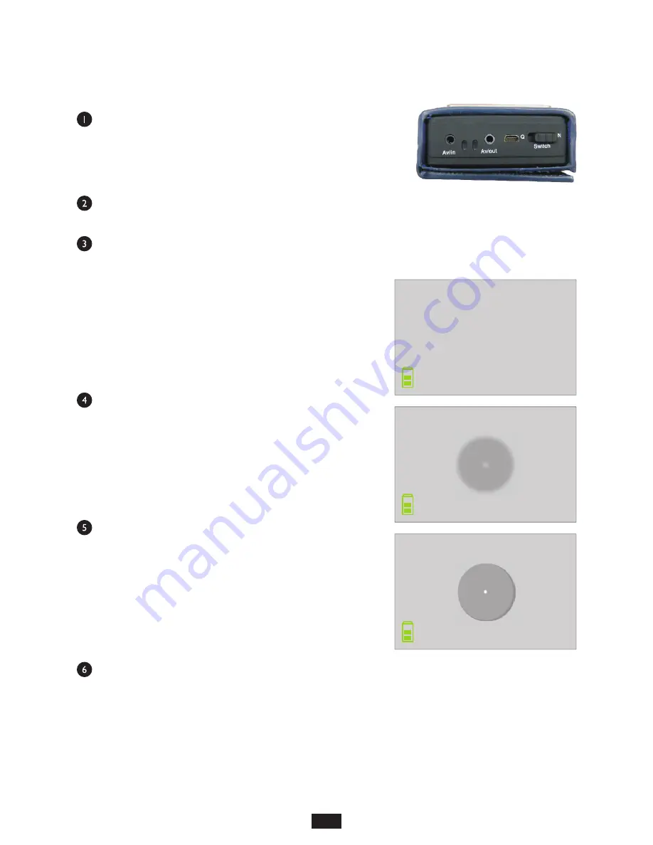
With the unit powered OFF, connect the probe to the side of the
unit.
The probe pins are labeled OUT and IN to correspond with the
OUT and IN jacks on the side of the unit.
Attach the appropriate probe tip according to the connector port
or ferrule size that will be inspected. Several probe tip options are included with the VS-400-H.
Power ON the VS-400-H. The LCD display will initially show a test pattern.
A blank screen will appear that includes the current time and
date in the upper right-hand corner, battery status in the
lower left-hand corner, and video recording time and
memory status in the lower right-hand corner.
Connect the probe to the connector or port to be inspected.
Initially the image may be out of focus.
Using the focus adjustment wheel on the probe, focus the
image on the LCD display.
If any obstructions are found on the image, especially on the
core / cladding area, remove the probe from the connector/port to clean the endface. Then re-connect
the probe to re-inspect.
4
15
2016/07/07 08:48:23
00:00:00
7380 M
2
08:48:30
016/07/07
00:00:00
7380 M
2
08:48:35
016/07/07
00:00:00
7380 M


