Multidis SFQ
Technical description
•
The flow indicators in the flow
distributor must be in the fully open
position (factory setting). They do not
serve to set the flow rates!
•
The position of the indicator ring in
the sight glass has no direct relation
to the flow rate set on the QM valve
insert.
Install ball valves in front of the flow
distributor/return collector to shut off
the supply and return pipe.
1
2
3
4
5
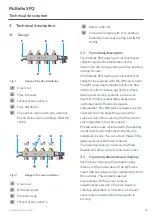
Fig. 3:
Design of the QM valve insert
1
Presetting key
2
Protection cap
3
Handwheel
4
Return collector
5
Connection nipple
1
2
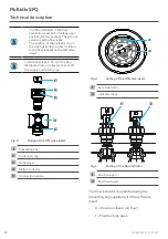
Fig. 4:
Setting of the QM valve insert
1
Set value l/min
2
Indicator mark
1
2
Fig. 5:
Setting of the flow indicator
1
Position open
2
Position closed
The flow indicator is operated using the
presetting key supplied with the QM valve
insert.
•
0 =
Position closed (no flow)
•
I = Position fully open
20
140495282-V01.09.2021
Summary of Contents for Multidis SFQ
Page 1: ...Multidis SFQ Notice d utilisation Operating instructions Betriebsanleitung DE FR EN ...
Page 2: ......
Page 4: ...Seite Multidis SFQ Inhaltsverzeichnis 10 Demontage und Entsorgung 13 4 140495282 V01 09 2021 ...
Page 14: ......
Page 16: ...Page Multidis SFQ Contents 10 Removal and disposal 24 16 140495282 V01 09 2021 ...
Page 25: ......
Page 26: ......
Page 28: ...Page Multidis SFQ Contenu 10 Démontage et traitement de déchets 38 28 140495282 V01 09 2021 ...


