Multidis SFQ
Installation
6. Installation
NOTICE
Damage to property due to lubricants!
Seals can be destroyed by the use of greases
or oils�
!
Do not use greases or oils during
installation.
!
If necessary, flush dirt particles and
grease and oil residues out of the
pipework.
!
When selecting the operating medium,
observe the general state of the art (e.g.
VDI 2035).
!
If the operating medium is
contaminated, install a strainer in the
supply pipe (VDI 2035).
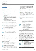
The brackets enable mounting on the wall or
in the cabinet.
1.
Mount the flow distributor (at the top) and
the return collector (at the bottom) into
the sound-absorbing brackets.
2.
Mount them onto the wall or in the
cabinet.
The supply and return pipe can be
connected from either the left or right
hand side�
7. Commissioning
7.1
Filling, bleeding and leak testing of
the installation
Before commissioning, you have to fill and
bleed the installation.
1.
Close the ball valves in front of the flow
distributor and the return collector.
2.
Fully open the QM valve inserts.
3.
Set the handwheel with the presetting key
to the set value 5. The G ¾ connection of
the fill and drain cock is suitable for the
connection of a commercially available
DN 15 hose fitting.
4.
Apart from the circuit to be filled, close all
valve inserts QM using the protection cap.
5.
Flush and fill each circuit one after the
other via the fill and drain cock at the
return collector to the fill and drain cock at
the flow distributor.
6.
Carry out a leak test according to DIN EN
1264�
Record the tightness and the test
pressure in a test record. You can find
the test record as a copy template on
our website.
•
Visit www.oventrop.com.
•
There, select the menu option
DOWNLOADS & SOFTWARE.
•
Proceed to BROCHURES.
•
Select SURFACE HEATING AND
COOLING COFLOOR.
•
You can find the test record in our
brochure "Cofloor Surface heating and
cooling systems/Systems with
distributor/collector".
7.2
Protection cap
The Multidis SFQ heating circuit distributor/
collector is supplied with a protection cap (see
Fig. 2 on page 19) made of plastic on the
QM valve insert. On the one hand, it protects
the valve spindle, and on the other hand, it can
be used to manually adjust the valve stroke
during the construction phase.
f
Turning clockwise
Z
The valve insert closes and the
heat supply is reduced
f
Turning anticlockwise
Z
The valve insert opens and the
heat supply is increased
23
140495282-V01.09.2021
Summary of Contents for Multidis SFQ
Page 1: ...Multidis SFQ Notice d utilisation Operating instructions Betriebsanleitung DE FR EN ...
Page 2: ......
Page 4: ...Seite Multidis SFQ Inhaltsverzeichnis 10 Demontage und Entsorgung 13 4 140495282 V01 09 2021 ...
Page 14: ......
Page 16: ...Page Multidis SFQ Contents 10 Removal and disposal 24 16 140495282 V01 09 2021 ...
Page 25: ......
Page 26: ......
Page 28: ...Page Multidis SFQ Contenu 10 Démontage et traitement de déchets 38 28 140495282 V01 09 2021 ...


