background image

Form No. OVmm-0113

10

OPERATION

Programming Menu Items

Use the following procedure to edit or create menu items. This

procedure requires access to password-protected screens and

should be performed by authorized personnel only.

NOTE: The USB port allows the uploading of pre-programmed

menu items from an external USB drive. Refer to the

“Uploading from a USB Drive” procedure in this section

for details.

1. From the main menu screen on either touchscreen, touch

the BaCK arrow. 

• a password keypad will appear on the touchscreen.

2. Input the password using the keypad, and touch ENTER. 

• The Home screen will appear on the touchscreen.
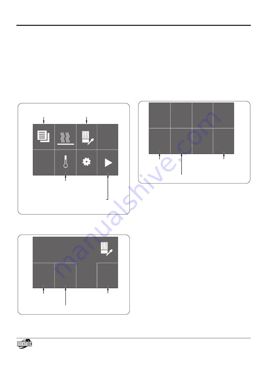
Home Screen

3. Touch  the  chef’s  hat/spoon  icon  to  access  the  menu

Development screen.

menu Development Screen

Touch to return to

Main Menu screen.

Touch to access

Setpoint Temperature screen

shown at startup.

Touch to access

Menu Development

screen.

Touch arrow to move slider assembly from 

left-to-right (right touchscreen shown).

Arrow will appear in opposite corner on left

touchscreen to move slider from right-to-left.

Menu Development

New

Edit

Back

Touch to edit an

existing menu item.

Touch to create

a new menu item.

Touch to return to

Settings screen.

4. Touch either NEW or EDIT to create or edit a menu item.

• a screen that looks like the main menu screen will appear. 
• If creating a new menu item, touch an empty box, and

the menu Item Settings screen will appear. If no empty

boxes  are  available,  touch  the  “down”  arrow  in  the

bottom right box to scroll to the next main menu screen.

If creating a new menu item in an existing Category,

touch the Category, then touch an empty box in the

Category menu screen.

• If editing an existing menu item, touch the desired menu

item, and the menu Item Settings screen will appear. If

editing a menu item in an existing Category, touch the

Category,  then  touch  the  desired  menu  item  in  the

Category menu screen.

menu Item Settings Screen

5. Touch each “setting” box on the menu Item Settings screen

to edit the corresponding setting. Settings include item

name, cook time, top blower percentage, bottom blower

percentage, cook temperature, and number of stages.

• Touching a “setting” box will bring up a keypad specific

to the setting. Enter the desired value using the keypad,

then touch ENTER to return to the menu Item Settings

screen. 

• menu item names can have up to 16 characters.
• Each menu item can be programmed to have up to

three stages, depending on the food product. Stages are

programmed  with  unique  settings  to  create  a

customized cooking sequence for the menu item.

NOTE: It is not necessary to create stages for a menu item if it

is not required by the food product. If unique stages are

not required, leave the cook time setting for stages 2

and 3 at zero.

• To  delete  a  menu  item,  change  the  item  name  to

DELETE (all caps) and touch ENTER to return to the

menu Item Settings screen. Touch BaCK/SaVE on the

menu Item Settings screen to confirm deletion.

6. When  the  menu  item  settings  are  complete,  touch

BaCK/SaVE  to  save  settings  and  return  to  the  menu

Development screen.

• To continue programming, repeat steps 4 and 5 of this

procedure.

• If programming is complete, touch BaCK on the menu

Development screen to return the Home screen.

Start

Cookies

Back/

Save

Bottom

Blower

50%

Stage 1/3

(next)

Top

Blower

50%

Temp

 500 F

Time

 1:00

Touch to save settings and return

to Menu Development screen.

Touch to start

the menu item

cooking sequence.

Touch to access settings

for next stage. 

Total Restaurant Supply - https://totalsupply1.com - Toll Free 1-800-944-9304 - Local 507-288-9454

2940 Hwy 14 W, Rochester, MN 55901

Summary of Contents for Matchbox M1313

Page 1: ...tante información sobre seguridad concerniente al mantenimiento uso y operación de este producto Si usted no puede entender el contenido de este manual por favor pregunte a su supervisor Almacenar este manual en una localización segura para la referencia futura Ne pas utiliser cet équipement sans avoir lu et compris le contenu de ce manuel Le non respect des instructions contenues dans ce manuel p...

Page 2: ...formance Every unit is inspected and tested thoroughly prior to shipment Important Owner Information 2 Introduction 2 Important Safety Information 3 Model Description 4 Model Designation 5 Specifications 5 Plug Configurations 5 Electrical Rating Chart 5 Dimensions 6 Installation 7 General 7 Operation 8 General 8 menu Item Information 8 Startup 8 Cooking 9 Shutdown 9 Programming menu Items 10 Chang...

Page 3: ...o determine and install proper voltage and size electrical receptacle Unit must be grounded properly Failure to ground unit properly could result in serious personal injury or death Turn off Standby switch allow unit to cool and unplug unit turn OFF Main Disconnect switch before performing any cleaning adjustments or maintenance DO NOT submerge or saturate with water Unit is not waterproof Do not ...

Page 4: ...anup a USB port allows the uploading of pre programmed menu items installation of software updates and opportunity for service diagnostics a 6 1829 mm cord and plug set is standard NOTE To prevent delay in obtaining warranty coverage complete online warranty registration See the ImPORTaNT OWNER INFORmaTION section for details Touchscreens Left Platform Oven Chamber Right Platform Standby Switch US...

Page 5: ...the unit See the label for the serial number and verification of unit electrical information Plug Configurations Units are equipped with an electrical cord and plug appropriate for the electrical rating of the unit Unit must be connected to a dedicated circuit ELECTRIC ShOCK hAzARD Plug unit into a properly grounded electrical receptacle of the correct voltage size and plug configuration If plug a...

Page 6: ...9 5 16 490 mm 26 659 mm 32 15 16 835 mm 20 7 8 530 mm 20 508 mm Form No OVmm 0113 6 SPECIFICATIONS Dimensions Specification Label on left side of unit A B C F D G H G E Front View Side View Top View Power Cord Cook Surface Dimensions Model M1313 13 W x 13 D x 3 1 8 H 330 x 330 x 79 mm Model M1718 17 W x 18 D x 3 1 8 H 431 x 457 x 79 mm Dimensions model m1718 shown Total Restaurant Supply https tot...

Page 7: ...s on each side of oven chamber Platforms are not designed to support weight of unit Lift from underneath oven chamber only 6 Place the unit in the desired location make sure to lift from underneath the front and rear of the oven chamber only Locate the unit in an area where the ambient air temperature is constant and a minimum of 70 F 21 C make sure the unit is at the proper counter height in an a...

Page 8: ...en shows the available setpoint temperatures Startup Screens WARNING CAUTION Breakfast Temperature 425 F Dinner Temperature 525 F Lunch Temperature 400 F UI X XX RB Y YY LEFT TOUCHSCREEN RIGHT TOUCHSCREEN Touch arrow to move slider assembly from right to left Touch arrow to move slider assembly from left to right Touch desired setpoint temperature 3 Touch the desired setpoint temperature on the ri...

Page 9: ...ve the cooked food product Queued Item Cooking Continuous Cooking 1 Perform steps 1 3 of the Single Item Cooking procedure in this section The slider assembly moves the food product into the oven chamber and the cooking sequence begins 2 Using a paddle pan gripper or other utensil place the next food product onto the opposite cooking surface that is now outside of the oven chamber 3 Touch the desi...

Page 10: ...e desired menu item and the menu Item Settings screen will appear If editing a menu item in an existing Category touch the Category then touch the desired menu item in the Category menu screen menu Item Settings Screen 5 Touch each setting box on the menu Item Settings screen to edit the corresponding setting Settings include item name cook time top blower percentage bottom blower percentage cook ...

Page 11: ...e the following procedure to edit or create the setpoint temperature s available at oven startup This procedure requires access to password protected screens and should be performed by authorized personnel only 1 From the main menu screen on either touchscreen touch the BaCK arrow a password keypad will appear on the touchscreen 2 Input the password using the keypad and touch ENTER The Home screen...

Page 12: ... temperatures 2 Remove the cover from the USB port above the Standby switch and insert the USB drive into the port 3 Touch the upper left hand corner on the left touchscreen a password keypad will appear on the touchscreen Back Dinner Breakfast Lunch 525 425 400 Touch setpoint name box to edit create name of setpoint Touch setpoint temperature box to edit create setpoint temperature Touch to retur...

Page 13: ...ntion when cleaning the oven chamber will void the warranty CAUTION Use non abrasive cleaners and cloths only Abrasive cleaners and cloths could scratch finish of unit marring its appearance and making it susceptible to soil accumulation 1 Turn off the Standby switch and allow unit to cool Cooling fans will operate until the oven chamber temperature drops below 140 F 60 C 2 after the cooling fans ...

Page 14: ...on when cleaning the oven chamber will void the warranty Cleaning the air Filters 4 Remove and clean the upper and lower jet plates inside the oven chamber To clean the jet plates a Unlatch and open the oven door so that the inside of the oven chamber is exposed b Remove the upper and lower jet plates Remove the plates by pulling the handles straight out of the oven c Spray Chemco Dirt Buster III ...

Page 15: ...n Indicator Light CHECK FANS Indicator Light ambient air temperature is over 95 F 35 C Light will illuminate in ambient temperatures over 95 F 35 C Verify light shuts off after ambient temperature drops below 95 F 35 C consistently If not see Probable Causes listed below air filters are dirty Check air filters and clean if necessary Refer to monthly Cleaning procedure in maINTENaNCE section Coolin...

Page 16: ...n Cleaner P N 0700 8001 Use Chemco Dirt Buster III Oven Cleaner to clean cooking grease and residue safely from the slider system end caps jet plates and oven chamber Total Restaurant Supply https totalsupply1 com Toll Free 1 800 944 9304 Local 507 288 9454 2940 Hwy 14 W Rochester MN 55901 ...

Page 17: ...g or misapplication improper installation lack of or improper cleaning or application of improper voltage 2 LIMITATION OF REMEDIES AND DAMAGES Ovention s liability and Buyer s exclusive remedy hereunder will be limited solely at Ovention s option to repair or replacement by an Ovention authorized service agency other than where Buyer is located outside of the United States Canada United Kingdom or...

Page 18: ...Form No OVmm 0113 18 NOTES Total Restaurant Supply https totalsupply1 com Toll Free 1 800 944 9304 Local 507 288 9454 2940 Hwy 14 W Rochester MN 55901 ...

Page 19: ...Form No OVmm 0113 19 NOTES Total Restaurant Supply https totalsupply1 com Toll Free 1 800 944 9304 Local 507 288 9454 2940 Hwy 14 W Rochester MN 55901 ...

Page 20: ...Ey Jay Hill Repair Fairfield 973 575 9145 Service Plus Flanders 973 691 6300 NEW yORK acme american Repairs Inc Brooklyn 718 456 6544 alpro Service Co Brooklyn 718 386 2515 appliance Installation Buffalo 716 884 7425 Duffy s Equipment Services Inc Buffalo 800 836 1014 3Wire Northern Plattsburgh 800 634 5005 Duffy s Equipment Services Inc Sauquoit 800 836 1014 J B Brady Inc Syracuse 315 422 9271 NO...

Reviews: