


User Manual of Network Fisheye Camera
60
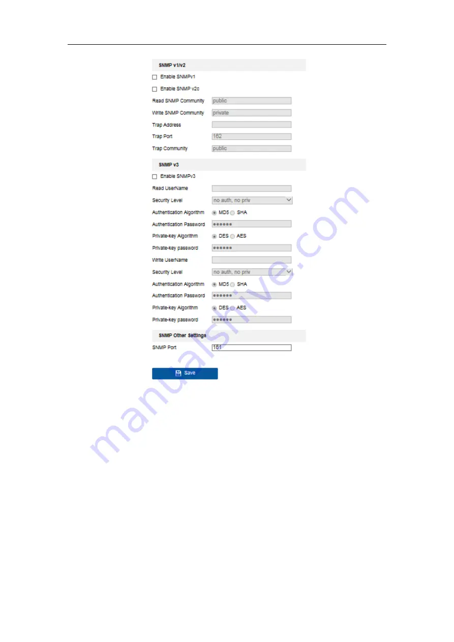
Figure 5-28
SNMP Settings
2.
Check the checkbox of Enable SNMPv1, Enable SNMP v2c, or Enable SNMPv3 to
enable the feature correspondingly.
3.
Configure the SNMP settings.
Note:
The settings of the SNMP software should be the same as the settings you
configure here.
4.
Click
Save
to save and finish the settings.
Note
:
A reboot is required for the settings to take effect.


