background image

•  Line up either the ACA or DCA on its respective side of the FX, starting at the top.
•  To attach a DCA, line up its two screw holes with the upper and lower right DCC screw holes.
•  When lined up, loosely install the upper screw to hold the DCA in place.
•  Slide the DC chassis over snug against the DCA (the screw slots in each chassis are oval-shaped  
  to allow for movement) so the DCA lines up with the conduit adapter hole on the chassis.
•  Install the plastic bushing from inside the chassis into the DCA (see Figure 11).
•  After inserting the bushing into the top DCA, the remaining DCA will line up and the other  
  bushing installed.
•  With all the DCA’s aligned with the DC chassis and the bushings installed, tighten the DC Chassis  
  screws against the FW-MP.
•  The single screws holding each DCA in place can be removed later when the DCC’s are installed.

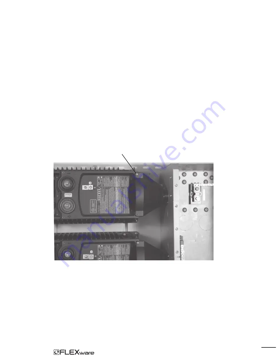
A single screw holds each DCA conduit adapter in place. Slide the DC chassis against each DCA 
and line it up with the plastic bushing.

Figure 10: 

DCA in place

10

Summary of Contents for FLEXware 500

Page 1: ...500 User s Guide Includes Mounting Installation and Product Registration...

Page 2: ...FLEXware 500 Manual Copyright 2006 All rights reserved Disclaimer UNLESS SPECIFICALLY AGREED TO IN WRITING OUTBACK POWER SYSTEMS a MAKES NO WARRANTY AS TO THE ACCURACY SUFFICIENCY OR SUITABILITY OF AN...

Page 3: ...most installations the negative battery conductor should be bonded to the grounding system at one and only one point in the DC system All installations must comply with all national and local codes an...

Page 4: ...nstallations along with the desired AC and DC disconnects FLEXware 500 which supports up to two FXs and two MX Charge Controllers accommodating both split phase and or higher power output as needed FL...

Page 5: ...le when mounting space is limited Note Although FLEXware 500 supports two MX Charge Controllers both locations top and side are shown in Figure 1 Getting to Know FLEXware 500 IOB Kit FW500 AC FW Mount...

Page 6: ...Front View Side View Figure 2 Knockouts and Dimensions 11 40 18 27 12 06 3...

Page 7: ...Transformer installed Note Be sure you have all the parts required for your intended system installation As every installation is different consult with your dealer or installer for further informati...

Page 8: ...nstallation FLEXware 500 is designed for mounting on the FLEXware Mounting Plate FW MP Although the components can be secured to other surfaces the FW MP is an engineered platform designed for the FLE...

Page 9: ...FXs Start with the top FX Hang the FX on the hanging screws but continue to hold onto it Loosely install four M6 X 20 mm screws included with the FW MP one in each corner tighten them when all four a...

Page 10: ...d DC chassis before installing either of them If needed the back knockouts must be removed before installation Figure 6 Removing chassis side knockouts When installing the AC chassis and the DC chassi...

Page 11: ...assis up to its respective mounting holes on the FW MP Place one M6 X 10mm machine screw provided with the FW MP in each corner tightening only enough to keep the chassis in place AC side DC side Figu...

Page 12: ...ring Cover DCC Figure 8 AC and DC chassis mounted With each chassis loosely mounted the AC Conduit Adapter ACA and DC Conduit Adapter DCA are installed on each FX Remove the clear plastic AC cover and...

Page 13: ...duit adapter hole on the chassis Install the plastic bushing from inside the chassis into the DCA see Figure 11 After inserting the bushing into the top DCA the remaining DCA will line up and the othe...

Page 14: ...ounting to the FX Line each ACA up with its conduit hole in the AC chassis When aligned move the AC chassis snug against the ACAs after the ACA installations Press a 1 plastic bushing from inside the...

Page 15: ...AC Chassis and DC Chassis installed the breaker brackets AC din rail s and optional AC and DC breakers can be installed Please see the individual Input Output Bypass Breaker IOB kit for instructions E...

Page 16: ...allowing them to be mounted directly to the side of the enclosure without the need for additional mounting brackets Mounting brackets are available for top installation of all MX models and for side...

Page 17: ...s using three 10 X 3 8 sheet metal screws included in the hardware kit Two are inserted from inside the MX and the third through the hanger on the top of the MX MX Knockouts Figure 13 MX Charge Contro...

Page 18: ...OutBack HUB allows the FX Series Inverter Chargers MX60 Charge Controllers and MATE to communicate with each other It attaches to the outside of the FW500 AC hardware included with the HUB Figure 14 O...

Page 19: ...Figure 15 Wiring Diagram 17...

Page 20: ......

Page 21: ......

Page 22: ......

Page 23: ...______ Telephone Number ______________________________________________________________ E mail _________________________________________________________________________ Sold by ________________________...

Page 24: ...European Sales Office Barcelona Espa a 34 600 843 845 19009 62nd Avenue NE Arlington WA USA 1 360 435 6030 www outbackpower com 900 0061 1...

Reviews: