


User manual for OTTO HEUSS universal stop motor PCB RM-2
Otto Heuss GmbH
Page
5
of
8
4.2
Plug-IN PCB
The wiring of the motors to the control cabinet is described in the respective manual of the
control cabinet.
The connections "Schalter"[Switch] and "Trem. Poti." are available on the side of the board, as
well as for the surface-mounted version.
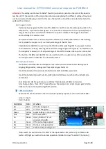
4.3
Fuse
There is a fuse on both versions of the circuit. Depending on the version, this can
be different in the factory. This is the fuse type "mini flat plug fuse".
5
Setting the dip-switch
The function modes are set by means of dip switches. After changing the dip switches, the
board must be disconnected from the power supply to accept the new setting.
Folgende Einstellungen sind möglich:
Switch 1 & 2:
Determining which basic function the magnet should have.
Switch 3:
When this switch is ON, the input logic is inverted. With a slider motor, this is used to
turn the working direction of ON and OFF. With tremulant and coupling magnets, this
switch causes the magnet to operate when no RS/RzO signal is present and vice
versa.
Switch 4:
If this switch is ON, the status of the "Kontakt"[Switch] connection is inverted. (Setter
feedback dual stop action). For this, a switch must be connected to the two
"Schalter" [Switch] connection points on the side of the board.
Switch 5:
If this switch is set to ON, the inputs Setzer-AN [Setter-ON] and Setzer-AB [Setter-
OFF] operate by a negative signal (GND). Usually a plus-switched control signal from
the stop switch or setter is used, this function can be used to switch to a negative
signal. The input "Funktion" is always with negativ (GND) signal.
If this dip-switch is switched on, the LEDs of the inputs Setzer-AN and Setzer-AB light
up inverted to normal operation. The maximum resistance to ground must not
exceed 1kΩ.
Switch 6:
If this switch is set to ON, an End Boost is activated. In this case, after a short period
of time, the motor is energized with 100% of the voltage for a short period of time
for the function el. stop action and el. /mech. dual stop action. This function safely
pulls heavy sliders into the end position.
With smooth-running sliders, the end position is reached before the End Boost sets
in, so that this is not associated with additional noise.
1 2 3 4 5 6 7 Description
0 0
Stop motor el. stop action (RS/RzO permanent signal)
1 0
Stop motor el./mechanical dual action (RS/RzO pulse
signal)
0 1
Tremulant (RS/RzO permanent signal)
1 1
Coupler motor (RS/RzO permanent signal)
1
Turn working direction ON/OFF-OFF/ON
1
Microswitch turn output
1
Inputs ON and OFF negative input signal
1 Stop motor End-Boost
1 Temperature shutdown


