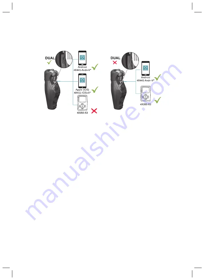
Important information for the products 3B5-X3/3B5-X3=ST and3B5-2/3B5-2=ST
Using the 4X350-X3 remote control is no longer possible on products with the marking"DUAL"
60
Page 1: ...Gebrauchsanweisung Benutzer 3 Instructions for use user 57 Genium X3 Bionic Prosthetic System 3B5 X3 3B5 X3 ST Genium X3 3B5 2 3B5 2 ST...
Page 2: ...2...
Page 3: ...stem 4 9 17 Hinweise zur Verwendung eines mobilen Endger ts mit der Cockpit App 4 10 17 Lieferumfang und Zubeh r 5 18 Lieferumfang 5 1 18 Zubeh r 5 2 19 Akku laden 6 19 Netzteil und Ladeger t anschlie...
Page 4: ...ooth der Prothese aus einschalten 8 3 33 Bluetooth ber die Cockpit App aus einschalten 8 3 1 34 Abfrage des Status der Prothese 8 4 34 Status ber die Cockpit App abfragen 8 4 1 34 Statusanzeige in der...
Page 5: ...en 15 42 Anh nge 16 45 Angewandte Symbole 16 1 45 Betriebszust nde Fehlersignale 16 2 46 Signalisierung der Betriebszust nde 16 2 1 46 Warn Fehlersignale 16 2 2 47 Fehlermeldungen beim Verbindungsaufb...
Page 6: ...Wichtige Information f r die Produkte 3B5 X3 3B5 X3 ST und 3B5 2 3B5 2 ST Bei Produkten mit der Kennzeichnung DUAL ist die Verwendung der Fernbedienung 4X350 X3 nicht mehr m glich 6...
Page 7: ...es Landes Bewahren Sie dieses Dokument auf Das Produkt Genium X3 Bionic Prosthetic System oder Genium X3 wird im Folgenden Pro dukt Prothese Kniegelenk Passteil genannt Diese Gebrauchsanweisung gibt I...
Page 8: ...rstand 3 Bestimmungsgem e Verwendung 3 1 Verwendungszweck Das Produkt ist ausschlie lich f r die exoprothetische Versorgung der unteren Extremit t einzu setzen 3 2 Einsatzbedingungen Das Produkt wurde...
Page 9: ...chnet die Quelle und oder die Art der Gefahr Die Einleitung beschreibt die Folgen bei Nichtbeachtung des Sicherheitshinweises Sollte es mehrere Folgen geben werden diese wie folgt ausgezeichnet z B Fo...
Page 10: ...Mode Basismodus mit Bewegungsmuster Piep und Vibrationssignal zur Anzeige der erfolgreichen Umschaltung in einen MyMode Ba sismodus Piep und Vibrationssignal zur erfolgreichen Umschaltung in den Tiefs...
Page 11: ...gelenk nicht unter extremen Bedingungen wie beim Tauchen oder bei Spr ngen ins Wasser Das Knie gelenk und der AXON Rohradapter sind f r den Einsatz unter Wasser ausgelegt maximale Dauer und Wassertief...
Page 12: ...Verwendung exoprothetischer Kniegelenke kann es in Folge von servomotorisch hy draulisch pneumatisch oder bremslastabh ngig ausgef hrten Steuerungsfunktionen zu Bewe gungsger uschen kommen Die Ger usc...
Page 13: ...eil Ladeger t keinen mechanischen Vibrationen oder St en aus berpr fen Sie das Netzteil Ladeger t vor jedem Einsatz auf sichtbare Sch den HINWEIS Betrieb des Netzteils Ladeger ts au erhalb des zul ssi...
Page 14: ...annern f r Personen z B im Flughafenbereich oder anderen starken magnetischen und elektrischen St rquellen z B Hochspannungsleitungen Sender Trafostationen Sollten sich diese Aufenthalte nicht vermeid...
Page 15: ...lten des Produkts infolge Umschaltung in den bertempera turmodus Verbrennung durch Ber hrung berhitzter Bauteile Beachten Sie die einsetzenden pulsierenden Vibrationssignale Diese zeigen Ihnen die Ge...
Page 16: ...e vollst ndig belasten Lassen Sie sich in die korrekte Verwendung der Stehfunktion vom Orthop dietechniker und oder Therapeuten unterweisen Informationen zur Stehfunktion siehe Seite 26 VORSICHT Schne...
Page 17: ...2 ST WARNUNG Hohe mechanische Belastungen durch gew hnliche wie au ergew hnliche Situationen wie St rze berlastung des Knochens die u a zu Schmerzen Lockerung des Implantates Absterben von Knochengewe...
Page 18: ...ck wenn die Aktivit ten im MyMode beendet sind HINWEIS Zerst rung des mobilen Endger ts durch Sturz oder Wassereintritt Fehlfunktion des mobilen Endger ts Beachten Sie die Gebrauchsanweisung des mobil...
Page 19: ...des Akkus sind folgende Punkte zu beachten Zum Laden des Akkus ist das Netzteil 757L16 und das Ladeger t 4E60 zu verwenden Die Kapazit t des vollst ndig geladenen Akkus reicht bei durchschnittlicher B...
Page 20: ...Ring in einer anderen Farbe leuchten liegt ein Fehler vor siehe Seite 47 2 Der Ladevorgang wird gestartet Ist der Akku des Produkts vollst ndig aufgeladen leuchten an der Seite des Ladeger ts alle LED...
Page 21: ...Ladezustands w hrend des Ladevorgangs W hrend des Ladevorgangs wird der aktuelle Ladezustand durch die Anzahl der leuchtenden LED s seitlich am Ladeger t angezeigt Anzahl Ladezustand 0 0 10 1 10 30 2...
Page 22: ...et sein oder durch das Anlegen Abnehmen des Ladeger ts Blue tooth eingeschaltet werden Anschlie end ist Bluetooth f r die Dauer von ca 2 Minuten ein geschaltet W hrend dieser Zeit muss die App gestart...
Page 23: ...der Eingabe des Bluetooth PIN wird die Verbindung zum Passteil aufgebaut W hrend dem Verbindungsaufbau ert nen 3 Piepsignale und es erscheint das Symbol Ist die Verbindung hergestellt wird das Symbol...
Page 24: ...7 Anzeige und Benennung des aktuell gew hlten Modus z B 1 Basismodus 8 MuteModus ist aktiviert 9 Verbindung zum Passteil ist hergestellt Verbindung zum Passteil ist unterbrochen Es wird ver sucht die...
Page 25: ...ute dauern Anschlie end erscheint das Hauptmen mit dem Namen des verbundenen Passteils INFORMATION Sollte der Verbindungsaufbau zu einem Passteil nicht m glich sein folgende Schritte durchf h ren Fall...
Page 26: ...Beugerichtung Flexion fixiert Die Stehfunktion muss vom Orthop dietechniker freigeschaltet werden Zus tzlich muss vom Or thop dietechniker die Art der Sperre des Gelenks Bewusst Intuitiv festgelegt w...
Page 27: ...Vorw rtsbewegung des Prothesenbeins und eine hohe dy namische Belastung des Kniegelenks Wird aus der Laufbewegung heraus gestoppt werden die ge nderten Einstellungen wieder auf die Standardwerte zur c...
Page 28: ...ockpit App aktiviert sein siehe Seite 31 In der Sitzposition wird zus tzlich zum reduzierten Widerstand in Streckrichtung auch der Wider stand in Beugerichtung reduziert Dies erm glicht ein freies Sch...
Page 29: ...Streckung kommen und das Bein in R cklage gelangen In dieser Phase hat das Kniegelenk bereits den Beugewiderstand auf Maximum blockiert geschaltet Das Kniegelenk kann nicht weiter gebeugt sondern nur...
Page 30: ...derung der Protheseneinstellungen Ist eine Verbindung zu einem Passteil aktiv k nnen die Einstellungen des jeweils aktiven Mo dus mit der Cockpit App ge ndert werden INFORMATION F r das ndern der Prot...
Page 31: ...etechni kers ist markiert und kann bei einer ver nderten Ein stellung durch das Antippen der Schaltfl che Stan dard wiederhergestellt werden 8 2 2 bersicht der Einstellparameter im Basismodus INFORMAT...
Page 32: ...t rke 0 4 0 4 Lautst rke des Piepsignals bei Best tigungst nen z B Abfrage des Lade zustands MyMode Umschaltung In der Einstellung 0 werden die akusti schen R ckmeldungssignale deakti viert Warnsignal...
Page 33: ...l Dies k nnte notwendig sein um mit einem Bewegungsmuster in den Basismo dus zu schalten Tonh he 1000 Hz 4000 Hz 1000 Hz 4000 Hz Tonh he des Piepsignals bei Best ti gungst nen Lautst rke 0 4 0 4 Lauts...
Page 34: ...1 Bei verbundenem Passteil im Hauptmen auf das Symbol tippen 2 Im Navigationsmen auf den Eintrag Status tippen 8 4 2 Statusanzeige in der Cockpit App Men eintrag Beschreibung m gliche Aktionen Tag Tag...
Page 35: ...s ber die Cockpit App ein ausschalten Tiefschlafmodus einschalten 1 Bei verbundenem Passteil im Hauptmen auf das Symbol tippen Das Navigationsmen wird ge ffnet 2 Im Navigationsmen auf den Eintrag Funk...
Page 36: ...der Stand zur Schwungphase Da die DSC stets die Kniefunktion ber wacht sind multidirektionale Bewegungen und auch R ckw rtsgehen ohne Gefahr der Aufhe bung des Standphasenwiderstands m glich Adaptive...
Page 37: ...im Basismodus verf gbar oder durch das Anlegen Abnehmen des Ladeger ts Bluetooth eingeschaltet werden Anschlie end ist Bluetooth f r die Dauer von ca 2 Minuten eingeschal tet W hrend dieser Zeit muss...
Page 38: ...f hren MyMode 1 MyMode 2 3x 1s MyMode 1 4x MyMode 2 2x MyMode 1 3x MyMode 2 1x 1x 1 Das Prothesenbein leicht nach hinten stellen Schrittstellung 2 Unter st ndigem Bodenkontakt entsprechend dem gew nsc...
Page 39: ...uhig halten Ein Piep und Vibrationssignal ert nt um die Erkennung des Bewegungsmusters zu be st tigen INFORMATION Ert nt dieses Piep und Vibrationssignal nicht wurden die Voraus setzungen beim Wippen...
Page 40: ...onstanter Standphasen Flexionswiderstand mit der M g lichkeit zur Schwungphasenausl sung eingestellt Die Schwungphasensteuerung und der Standphasen Extensionswiderstand sind je nach Art des Fehlers ve...
Page 41: ...r Gew hrleistung der EMV Sicherheit m ssen regelm ige Wartungen Servicein spektionen im Intervall von 12 Monaten durchgef hrt werden Die F lligkeit einer Wartung wird durch R ckmeldungen nach dem Abst...
Page 42: ...ichtlinie 1999 5 EG f r Funkanlagen und Telekommunikationsendeinrichtungen Die Konformit tsbewertung wurde vom Hersteller nach Anhang IV der Richtlinie durchgef hrt Nur g ltig f r die Produkte 3B5 2 3...
Page 43: ...ng steht 500 Ladezustand nach 1 Stunde Ladezeit 30 Ladezustand nach 2 Stunden Ladezeit 50 Ladezustand nach 4 Stunden Ladezeit 80 Ladezustand nach 8 Stunden Ladezeit vollst ndig geladen Verhalten des P...
Page 44: ...kpit 4X441 Andr V Unterst tztes Betriebssystem ab Android 4 0 3 Internetseite f r den Download https www ottobock com cockpitapp Daten bertragung Funktechnologie Bluetooth 2 0 Reichweite ca 10 m 32 8...
Page 45: ...n Maximale Tiefe 3 m Maximale Zeit 1 Stunde Dieses Produkt darf nicht berall mit unsortiertem Hausm ll entsorgt werden Eine nicht den Bestimmungen Ihres Landes entsprechende Entsorgung kann sich sch d...
Page 46: ...der Piep und Vibrationssi gnale INFORMATION Bei der Einstellung des Parameters Lautst rke in der Cockpit App auf 0 erfolgt keine Ausga be der Piepsignale siehe Seite 30 Piepsignal Vibrations signal Zu...
Page 47: ...nicht betriebsbereit Gehen mit Einschr nkung m glich Der ver nderte Beugewiderstand muss beachtet werden Das Produkt muss umge hend durch einen Ortho p dietechniker berpr ft werden 10 x lang 10 x lang...
Page 48: ...en ob der l nderspezifi sche Steckeradapter vollst ndig am Netzteil eingerastet ist Steckdose ohne Funktion Steckdose mit einem anderen Elektroger t pr fen Netzteil defekt Das Ladeger t und Netzteil m...
Page 49: ...r der Ladeeinheit an der Prothese verrin gern Der LED Ring blinkt rot Die Prothese wird nicht geladen Ladeger t defekt Fehler durch Ab und Anstecken des Netz teils beheben Sollte der Fehler be stehen...
Page 50: ...en gespeicherten Passteilen das richtige Passteil ge w hlt 16 2 4 Statussignale Ladeger t angelegt LED am Netzteil Status LED am Ladeger t Ereignis Netzteil und Ladeger t betriebsbereit Ladeger t noch...
Page 51: ...bsehbarer Zeit aufgesucht werden Dieser lei tet die Prothese falls erforder lich an eine autorisierte Otto bock Servicestelle weiter Die Verwendung ist uneinge schr nkt m glich M glicher weise erfolgt...
Page 52: ...r Das Produkt Genium X3 Bionic Prosthetic System 3B5 X3 Genium X3 3B5 2 ist f r den Gebrauch in anderen als Wohneinrichtungen und solchen bestimmt die unmit telbar an ein ffentliches Nie derspannungsn...
Page 53: ...4 11 5 UT 95 Einbruch der UT f r 1 2 Periode 40 UT 60 Einbruch der UT f r 5 Perioden 70 UT 30 Einbruch der UT f r 25 Perioden 5 UT 95 Ein bruch der UT f r 5 s nicht anwendbar Die Qualit t der Ver sor...
Page 54: ...ht anwendbar Abgestrahlte HF St r gr en gem IEC 61000 4 3 3 V m 80 MHz bis 2 5 GHz 12 V m 80 MHz bis 1 GHz 3 V m 1 GHz bis 2 5 GHz Tragbare und mobile Funkger te sollten in keinem geringeren Ab stand...
Page 55: ...msetzung des Produkts Genium X3 Bionic Prosthetic System 3B5 X3 Genium X3 3B5 2 Tabelle 6 Empfohlen Schutzabst nde zwischen tragbaren und mobilen HF Telekommu nikationsger ten und dem Produkt Genium X...
Page 56: ...ng ermittelt werden die zur jeweiligen Spalte geh rt wobei P die maximale Nennleistung des Senders in Watt W nach Angabe des Senderherstellers ist Anmerkung 1 Bei 80 MHz und 800 MHz gilt der h here Fr...
Page 57: ...use of a mobile device with the cockpit app 4 10 71 Scope of Delivery and Accessories 5 72 Scope of delivery 5 1 72 Accessories 5 2 72 Charging the battery 6 72 Connecting the power supply and battery...
Page 58: ...odes 8 2 3 86 Turning Bluetooth on the prosthesis on off 8 3 87 Switching Bluetooth off on using the cockpit app 8 3 1 87 Querying the prosthesis status 8 4 88 Query status through cockpit app 8 4 1 8...
Page 59: ...ndices 16 99 Symbols Used 16 1 99 Operating states error signals 16 2 100 Signals for operating states 16 2 1 100 Warnings error signals 16 2 2 101 Error messages while establishing a connection with...
Page 60: ...Important information for the products 3B5 X3 3B5 X3 ST and 3B5 2 3B5 2 ST Using the 4X350 X3 remote control is no longer possible on products with the marking DUAL 60...
Page 61: ...product pros thesis knee joint component in the following These instructions for use provide you with important information on the use adaptation and handling of the product Only put the product into...
Page 62: ...ance 3 Intended use 3 1 Indications for use The product is to be used solely for lower limb exoprosthetic fittings 3 2 Conditions of use The product was developed for everyday use and must not be used...
Page 63: ...d as follows if more than one consequence is possible E g Consequence 1 in case of failure to observe the hazard E g Consequence 2 in case of failure to observe the hazard This symbol identifies activ...
Page 64: ...a MyMode basic mode Beep and vibration signal upon successfully switching to deep sleep mode Before activating mute mode note that these feedback signals will be deactivated For more information about...
Page 65: ...data see page 97 After contact with water hold the prosthesis with the sole of the foot facing up until the water has drained from the knee joint and AXON tube adapter After using the knee joint in a...
Page 66: ...during the lifecycle of the knee joint the knee joint should be inspected by the O P professional immedi ately 4 4 Information on the Power Supply Battery Charging CAUTION Charging the product without...
Page 67: ...for charging within the allowable temperature range The section Technical data contains information on the allowable temperature range see page 97 NOTICE Independent changes or modifications carried...
Page 68: ...stems body scanners or metal detectors watch for unexpected changes in the damping behaviour of the product In general monitor the product for unexpected changes in the damping behaviour when electron...
Page 69: ...should be inspected for damage by an O P professional If neces sary they will forward the product to an authorised Ottobock Service Center CAUTION Overloading due to activities with unusual loads Fall...
Page 70: ...For further information about the MyModes see the section MyModes see page 90 4 8 Notes on the safety modes CAUTION Using the product in safety mode Falling due to unexpected product behaviour becaus...
Page 71: ...ng due to changed damping behaviour as a result of unexpected switching to a MyMode Make sure you have been instructed in the proper use of the mobile device with the Cockpit app CAUTION Improper use...
Page 72: ...Pros thetic System with threaded connector or 1 pc 3B5 X3 Genium X3 Bionic Prosthet ic System with pyramid connector or 1 pc 3B5 2 ST Genium X3 with threaded connector or 1 pc 3B5 2 Genium X3 with py...
Page 73: ...Connect the round three pin plug of the power supply to the receptacle on the battery char ger see fig 2 so that the plug locks into place INFORMATION Ensure correct polarity guide lug Do not use forc...
Page 74: ...e page 104 6 3 Display of the current charge level 6 3 1 Display of battery charge level without additional devices INFORMATION The charge level cannot be displayed during the charging process e g by...
Page 75: ...tery charge level 0 0 10 1 10 30 2 30 50 3 50 70 4 70 90 5 90 6 3 4 Display of current charge level using remote control optional accessory Only when DUAL marking is not present see page 60 The curren...
Page 76: ...g the prosthesis upside down sole of the foot must point up or by connecting disconnecting the battery charger Bluetooth is then turned on for approx 2 minutes During this time the app must be started...
Page 77: ...component is established While the connection is being established 3 beep signals sound and the symbol appears The symbol is displayed when the connection has been established Once the connection has...
Page 78: ...Display and name of the currently selected mode e g 1 Basic Mode 8 Mute mode is activated 9 Connection to component has been established Connection to component has been interrupted The app is attemp...
Page 79: ...Once the connection has been established the data are read from the component This process may take up to a minute Then the main menu appears with the name of the connected component INFORMATION If e...
Page 80: ...d using the Cockpit app see page 85 The stance function standing mode is a functional supplement to the basic mode mode 1 This function makes it easier for example to stand on an inclined surface for...
Page 81: ...Flex is reduced to 0 The requirements to automatically switch to the running motion are fast for ward movement of the prosthetic leg and high dynamic load on the knee joint When stopping from the runn...
Page 82: ...ng the Cockpit app see page 85 In the sitting position the resistance in the flexion direction is reduced in addition to the reduction of resistance in the extension direction This makes it possible t...
Page 83: ...ly and position the leg too far backwards In this phase the knee joint has already set the flexion resist ance to maximum blocked The knee joint can no longer be flexed but only extended This ensures...
Page 84: ...be switched on to change the prosthesis settings If Bluetooth is switched off it can be turned on by turning the prosthesis upside down or by connecting disconnecting the battery charger Bluetooth is...
Page 85: ...normal gait cycle These parameters act as basic settings for automatically adjusting the damping behaviour to the current motion situation e g ramps slow walking speed etc The stance function sitting...
Page 86: ...2 3 Overview of adjustment parameters in MyModes CAUTION Improper use of the setting parameters in the MyModes Falling due to unexpected behaviour of the product because of changed damping behaviour...
Page 87: ...must be turned on in order to use the Cockpit app If Bluetooth is switched off it can be turned on by turning the prosthesis upside down function only available in basic mode or by connecting disconne...
Page 88: ...ional purposes only 8 5 Mute mode silent mode Activating mute mode silent mode turns off the audible feedback signals and the vibration sig nals However warnings in case of component errors are still...
Page 89: ...re always active and cannot be influenced The OPG function minimises the prosthesis wearer s prosthetic deviations from a harmonious gait pattern and promotes more biomechanically correct walking This...
Page 90: ...the O P professional can configure a Running MyMode which can be activated using the cockpit app or a move ment pattern In this mode every step will be performed as a running step with larger swing ph...
Page 91: ...When mute mode silent mode is activated no beep and vibration signals are generated INFORMATION If the Volume parameter is set to 0 in the Cockpit app see page 84 or if mute mode silent mode is activa...
Page 92: ...his confirmation signal does not sound the leg with the prosthesis was not correctly kept still or mute mode silent mode is activated Repeat the pro cess to correctly switch to the required mode For m...
Page 93: ...ode by charging the product 10 2 Mode for charging the prosthesis The product is non functional during charging The product is set to the flexion resistance of safety mode This may be low or high depe...
Page 94: ...storing the knee joint the knee head has to be extended The knee head must not be flexed Avoid extended disuse of the product use the product regularly 12 Cleaning 1 Rinse the product with clear fres...
Page 95: ...ade names or company names may be registered trademarks and are the property of the respective owners Should trademarks used in this document fail to be explicitly identified as such this does not jus...
Page 96: ...e equipment Caution Exposure to Radio Frequency Radiation This device must not be co located or operating in conjunction with any other antenna or transmit ter Responsible party Otto Bock Health Care...
Page 97: ...esistance Waterproof corrosion resistant Range of Bluetooth connection to mobile device max 10 m Weight of the prosthesis without tube adapter and Protective Cover approx 1 710 g Tube adapter Referenc...
Page 98: ...midity non condensing Protection rating IP40 Input voltage 12 V Wireless technology Proprietary protocol Frequency range 270 kHz to 450 kHz Modulation ASK load modulation Maximum output power EIRP 12...
Page 99: ...ising radiation Protection against penetration of solid foreign objects with a diameter greater than 1 mm no protection against water Dustproof protection against permanent submersion Maximum depth 3...
Page 100: ...d disconnected Beep signal Vibration signal Event 3x long Charging mode started 3 sec after connecting the battery charger 1x short 1x short Self test completed successfully product is operational Mod...
Page 101: ...Charge battery soon Remaining operating time approx 24 hours 5x long Battery charge level under 10 Charge battery soon Remaining operating time approx 6 hours 5x long 5x long repeated every 60 seconds...
Page 102: ...ngaged on the power supply Non functional socket Check socket with another electric appliance Defective power supply The battery charger and power supply must be inspected by an authorised Ottobock Se...
Page 103: ...rger or reduce the distance between the charger and the receiv er of the charging unit on the prosthesis The LED ring is flashing red The prosthesis is not being charged Defective battery charger Rese...
Page 104: ...omponents were stored was the correct component selected 16 2 4 Status signals Battery charger connected LED on power supply Status LED on battery charger Event Power supply and battery charger operat...
Page 105: ...nals may not be generated Battery charge level During the charging process the current battery charge level is indicated by the number of LEDs lit on the side of the charger LEDs 0 1 2 3 4 5 Battery c...
Page 106: ...Genium X3 Bionic Prosthetic System 3B5 X3 Genium X3 3B5 2 is designed for operation in an electromagnetic environment as specified below The customer or user of the product Genium X3 Bionic Prostheti...
Page 107: ...enium X3 Bionic Prosthetic System 3B5 X3 Genium X3 3B5 2 with an uninterruptible power supply or bat tery Magnetic field at mains frequency 50 60 Hz according to IEC 61000 4 8 3 A m 3 A m Magnetic fie...
Page 108: ...applicable for the transmission fre quency Recommended safety distance d 0 3 P for 80 MHz to 800 MHz d 2 3 P for 800 MHz to 2 5 GHz where P is the nominal output of the transmit ter in watts W accordi...
Page 109: ...the product Genium X3 Bionic Prosthetic System 3B5 X3 Genium X3 3B5 2 The product Genium X3 Bionic Prosthetic System 3B5 X3 Genium X3 3B5 2 is designed for operation in an electromagnetic environment...
Page 110: ...110...
Page 111: ...111...
Page 112: ...394 579 JP 5 968 591 JP 5 678 079 JP 6 109 793 Russia RU 2 404 730 RU 2 484 789 RU 2 533 967 RU 2 488 367 RU 2 508 078 RU2 572 741 Taiwan R O C Invention Patent No I386194 I459936 I442912 I494095 I551...