These instructions for use provide you with important information on the use,
adaptation and handling of the product.
Only put the product into use in accordance with the information contained
in the accompanying documents supplied.
2 Product description
2.1 Design
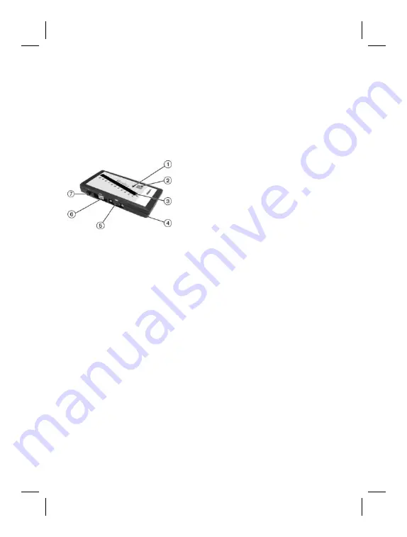
The product consists of the following components:
1. Operating indicator
2. ON button
3. Dual-channel LED display
4. Battery compartment
5. Electrode adapter connection
6. USB interface
7. Ground connection
2.2 Function
The 757M11=X-Change MyoBoy with USB connection is to be used for the
following purposes:
•
Depicting the muscle action potentials
•
Adjusting the Ottobock 13E200=* or 13E202=* electrodes
•
Muscle and coordination training
The patient's myoelectric muscle signals are recorded by Ottobock
13E200=* or 13E202=* electrodes connected via electrode adapters and
displayed on a dual-channel bar display. The MyoBoy is switched on by
pressing the ON button (item 2). After the hardware is switched on, a self-
test is conducted that automatically tests the functionality of the device and
the battery. The two bars are visible simultaneously during this process (item
3). The MyoBoy hardware is ready for use when the operating indicator LED
lights up (item 1).
Power is supplied by a 9 V block battery. It is located in the battery compart
ment on the back side (item 4). If the operating indicator LED is blinking,
this indicates that the 9 V block battery is empty. If the operating voltage
continues to drop, the MyoBoy hardware automatically switches off.
14


