background image


17 

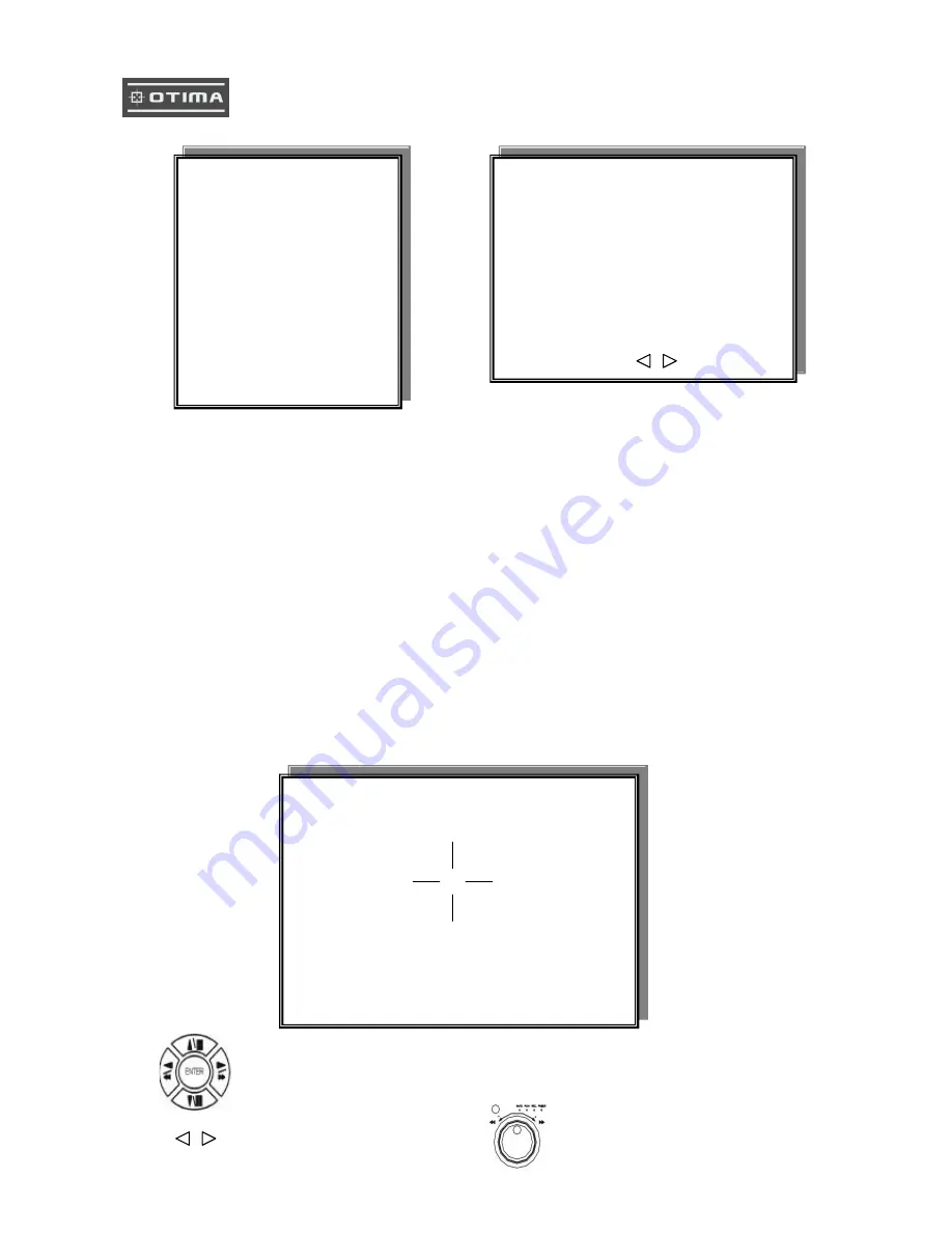
2. DATE-TIME SETUP 


1. Hour Type: 12H:MM:SS. 12 Hour Format / 24 Hour Format.   

2. Date Type: YY/MM/DD, MM/DD/YY, DD/MM/YY, YY/ENG/DD, ENG/DD/YY, DD/ENG/YY, YYYY/MM/DD, 

MM/DD/YYYY, DD/MM/YYYY, YYYY/ENG/DD, ENG/DD/YYYY, DD/ENG/YYYY.  

Y=Year. M=Month. D=Day. ENG=Month display in English. 

01=January; 02=February; 03=March; 04=April; 05=May; 06=June;   

07=July; 08= August; 09=September; 10= October; 11=November; 12=December. 

3. Date: 2003/01/01 

-


Please stop REC function first if you want to change the time. 


4. Time: 12/30/49  > Use direction button up/down choose position, values change button to change date 

and time values. 

5. Date and Time position setup:


Press direction button up/down/left/right to choose items or move date-time position. 

Press values change button or turn 

 inner-shuttle to change values.


**** DATE -TIME POSITION**** 


UP 

DOWN 

LEFT 

RIGHT 

ENTER for Default 

ESC to QUIT 

DATE-TIME SETUP PAGE 

1. HOUR TYPE: 

2. DATE TYPE 

3. DATE 2000 / 00 / 00 

4. TIME 

5. DATE-TIME POSITION SETUP 


MENU, ESC:EXIT,        :MODIFY 

MAIN SETUP PAGE 

1. HDD INFORMATION 

2. DATE-TIME SETUP 

3. DISPLAY   SETUP 

4. CAMERA   SETUP 

5. BUZZER


SETUP 

6. AUDIO     SETUP 

7. SYSTEM   SETUP 

8. ADVANCED SETUP 

Summary of Contents for DVR1601X

Page 1: ...1 Thank you for purchasing our product Please read this User s Manual before using the product Change without Notice 16 Channel Digital Video Recorder User s Manual...

Page 2: ...NG TO PREVENT FIRE OR SHOCK HAZARD DO NOT EXPOSE UNITS NOT SPECIFICALLY DESIGNED FOR Attention installation should be performed by qualified service Personnel only in accordance with the National Elec...

Page 3: ...s product contact your local dealer Strong recommendation on installation of the DVR unit 1 Check electricity at the place you want to install the DVR unit is stable and meets our electricity requirem...

Page 4: ...on 7 Procedure 7 Picture 10 Playback 12 Function Setup 14 Login 14 Basic Operation 15 1 HDD Information 16 2 Date Time Setup 17 3 Display Setup 18 4 Camera Setup 19 5 Buzzer Setup 23 6 Audio Setup 24...

Page 5: ...5 Unit Description of Front Panel...

Page 6: ...main call monitor output Audio Input 2 Channel Input 1 Channel Output Out 1 Left Out 2 Right Y C video monitor output 75 Ohm High Low Adjust HDD BAY connector RS232 connector Alarm connector Control k...

Page 7: ...0 9 8 7 6 5 4 3 2 1 25 24 23 22 21 20 19 18 17 16 15 14 13 12 11 Installation Procedure CH1 CH2 CH3 CH4 CH1 CH2 CH3 CH4 MONITOR VIDEO LENS VIDEO DC AC24V DC12 V P DC LEVEL Rear part of CAMERA CH1 CH2...

Page 8: ...rack the other one is fixed designed We recommend you to set the Removable Hard Disk as Slave Set the other one as the Master Internal Circuit 1 Make sure the HDD is MASTER 2 Make sure the cable conne...

Page 9: ...ECTION on the Rear Panel of the system and turn on the switch 8 Turn on the POWER Make sure the adaptor is 12V 5A 9 Detail setup in SYSTEM SETUP For detail setup refer to the instruction of SYSTEM SET...

Page 10: ...l screen mode with numeric buttons of live or playback mode then press ZOOM button to display screen Enlargement Use button to move position 3 Auto Mode Press AUTO button begins to screen auto sequenc...

Page 11: ...See the scheduled recording setup page 8 Motion detection Recording See the motion detection recording setup page 9 Key Lock function On the Live or Playback mode press lock Only numeric freeze auto p...

Page 12: ...ents sort by channel TYPE alarm events sort by type Press SEL button to change sort DELETE ITEM delete items by each PAGE delete each page ALL delete all items Playback PLAY PLAY SETUP PAGE EVENT LIST...

Page 13: ...d different 6 LAST xxxx xx xx xx xx xx The final date and time recording display When user stop record or go to menu at that moment is the last record 7 GOTO xxxx xx xx xx xx xx year month day Hour Mi...

Page 14: ...MENU 2 Password enter window pop up 3 Press numeric button to choose password then menu pop up 4 Remote controller function buttons are same as DVR panel function buttons LOGIN 1 Password Account Admi...

Page 15: ...r left right button And change the value with values change button or turn inner shuttle 4 Press ESC to go back to main menu or exit menu Notice 1 ADMIN level can setup all menu functions 2 USER level...

Page 16: ...d DVR system auto detect hard disk brand after power on Position IN DVR RACK 1 RACK 2 RACK 3 RACK 4 RACK 5 Status PARTIAL Frame Hard disk total image frame rate display Start The first recording date...

Page 17: ...to change the time 4 Time 12 30 49 Use direction button up down choose position values change button to change date and time values 5 Date and Time position setup Press direction button up down left r...

Page 18: ...e caption display mode on or off setup ON OFF 5 DVR STATUS DVR system Field record playback audio caption display mode on or off setup ON OFF 6 BORDER SET Border color WHITE YELLOW CYAN GREEN MAGENTA...

Page 19: ...19...

Page 20: ...choose items Press values change button or turn inner shuttle to change values CAMERA SETUP PAGE 1 COLOR SETUP 2 TITLE SETUP 3 SCREEN POSITION SETUP 4 V LOSS DISPLAY SETUP MENU ESC EXIT ENTER RUN CAM...

Page 21: ...l letter A B C D E F G H I J K L M N O P Q R S T U V W X Y Z Small letter a b c d e f g h i j k l m n o p q r s t u v w x y z Press direction button up down left right to choose items and position Pre...

Page 22: ...default 3 Press ESC button to quit SCREEN POSITION UP ENTER for Default ESC to QUIT DOWN LEFT RIGHT Press direction buttons up down left right to move screen position CAMERA SETUP 1 COLOR SETUP 2 TITL...

Page 23: ...7 ON OFF VLOSS 15 ON OFF VLOSS 08 ON OFF VLOSS 16 ON OFF VLOSS SETUP PAGE VLOSS FUNCTION VLOSS 01 VLOSS 09 VLOSS 02 VLOSS 10 VLOSS 03 VLOSS 11 VLOSS 04 VLOSS 12 VLOSS 05 VLOSS 13 VLOSS 06 VLOSS 14 VLO...

Page 24: ...ons up down to BUZZER SETUP items Press values change button or turn inner shuttle to change values BUZZER SETUP PAGE SYSTEM BUZZER ON BUTTON BUZZER ON ALARM BUZZER ON MOTION BUZZER ON VLOSS BUZZER ON...

Page 25: ...video channel NONE CH 1 16 7 OUTPUT CH Currently audio output is channel 1 2 8 OUTPUT VOLUME Audio volume 00 31 9 OUTPUT BALANCE Speaker balance 31 31 Press direction buttons up down to choose items...

Page 26: ...26 Press values change button or turn inner shuttle to change values...

Page 27: ...oard If user does not use keyboard to control then does not have to care Press direction buttons up down to choose items Press values change button or turn inner shuttle to change values MAIN SETUP PA...

Page 28: ...F RL1 RL2 BOTH 14 ALARM14 OFF RL1 RL2 BOTH 7 ALARM07 OFF RL1 RL2 BOTH 15 ALARM15 OFF RL1 RL2 BOTH 8 ALARM08 OFF RL1 RL2 BOTH 16 ALARM16 OFF RL1 RL2 BOTH BUZZER DURATION 0 999 SEC RECORD DURATION 0 999...

Page 29: ...999 SEC MOTION AREA SETUP MOTION RELAY SETUP ADVANCED SETUP PAGE 1 ALARM SETUP 2 MOTION SETUP 3 RECORD SETUP 4 TCP IP SETUP 5 PASSWORD SETUP 6 HDD FORMAT 7 HDD AUTO DETECT 8 FACTORY DEFAULT MOTION SE...

Page 30: ...area mode off CLEAR CH01 AREA MASK WALK ON MODE 1 2 3 4 SELECT CHANNEL MOVE SURSOR ENTER MASK OFF ESC KEY QUIT Press numeric to select channel Press value change button to change mode Press direction...

Page 31: ...F RL1 RL2 BOTH 8 RELAY08 OFF RL1 RL2 BOTH 16 RELAY16 OFF RL1 RL2 BOTH RL1 Relay 1 RL2 Relay 2 BOTH Both Relay 1 and Relay 2 MOTION SETUP MOTION FUNCTION CHANNEL NUMBER 1 DETECT NUMBER 2 SENSITIVITY 3...

Page 32: ...n or off ON OFF 5 RECORD POWER ON Always record after power on ON OFF 6 RESOLUTION Record image quality setup SUPER HIGH FINE NORMAL LOW ADVANCED SETUP PAGE 1 ALARM SETUP 2 MOTION SETUP 3 RECORD SETUP...

Page 33: ...ner shuttle to change values RECORD SETUP 1 HDD FULL 2 RECORD SCHEDULE 3 RECORD MOTION 4 RECORD ALARM 5 RECORD POWER ON 6 RESOLUTION SCHEDULE SETUP RECORD SPEED SETUP Press direction buttons up down t...

Page 34: ...00 20 00 21 00 22 00 23 00 00 30 01 30 02 30 03 30 04 30 05 30 06 30 07 30 08 30 09 30 10 30 11 30 12 30 13 30 14 30 15 30 16 30 17 30 18 30 19 30 20 30 21 30 22 30 23 30 THU 00 00 01 00 02 00 03 00...

Page 35: ...RECORD SPEED SETUP PAGE TOTAL SPEED FULL HALF 10 fps 5 fps 2 fps REC EVT REC EVT CH 01 A X P A X P CH 09 A X P A X P CH 02 A X P A X P CH 10 A X P A X P CH 03 A X P A X P CH 11 A X P A X P CH 04 A X...

Page 36: ...92 168 0 5 or use the factory default IP Press direction buttons up down left right to TCP IP items position Press values change button to change values ADVANCED SETUP PAGE 1 ALARM SETUP 2 MOTION SETU...

Page 37: ...he remote viewer to computer See the remote viewer page Port is depend on network company area but normally is 0080 port 5 PASSWORD SETUP 1 LEVEL Log In level ID type setup NONE ADMIN USER ADMIN is th...

Page 38: ...UTION ALL DATA IN HDD WILL BE DESTROYED PRESS ENTER TO FORMAT PRESS ESC TO CANCE L Press direction buttons up down to HDD FORMAT items position Press ENTER to in Press ENTER button to format hard disk...

Page 39: ...LEAR AND RESTORE FACTORY DEFAULT PRESS ENTER TO RESTORE PRESS ESC TO CANCEL Press ENTER button to restore Press ESC button to cancel ADVANCED SETUP PAGE 1 ALARM SETUP 2 MOTION SETUP 3 RECORD SETUP 4 T...

Page 40: ...storage capacity connect HDD Bay to DVR unit 1 Configuration of Bay connection to DVR unit Example DVR unit HDD Bay DVR UNIT Teratray 04 40 pins cables Total HDDs 6 HDDs DVR unit x2 hard disk inside...

Page 41: ...VR Or might make DVR record and playback function not stable 1 One Hard disk installation 2 Two Hard disk installation 3 Three Hard disk installation 4 Four Hard disk installation NOTICE 1 GO to HDD I...

Page 42: ...Million Monitoring Method Split Screen 1 4 9 16 Zoom Live PB Available x 2 zoom Sequence Available Screen Quality Full 720 H x 480 V Active Pixels NTSC 720 H x 576 V Active Pixel PAL 1 4 Screen 360 H...

Page 43: ...Image RS485 For Remote Controller x 2 Dry Contact Storage Internal 1 Or 2 HDD 3 5 IDE Interface Optional HDD Bay Support 4HDD 1 Unit Max 3 Units Power Supply DC Adapter 12V DC 5A Audio Input 2 x Input...

Page 44: ...44 2 DVR system...

Page 45: ...ore selected recorded pictures on HDD of client PC DVR does not adopted web browser method for access to DVR unit via Internet line and you must install Remote Viewer software included in the package...

Page 46: ...ny single channel or 4 channels at the same time You can select channel number from 1 to 4 to see pictures of selected channel If you selected 4 you swill see channel number from 1 to 4 are all activa...

Page 47: ...faster search speed is The absolute search speed is a little different from set value depending on data transfer rate of IP network b Scan Press scan button to enter into search window Using various o...

Page 48: ...ded 5 Channel selection button Press any one from 1 to 4 to see picture of corresponding channel if you first chose full screen button 2 6 Time selection button You can set time to search by dragging...

Page 49: ...recorded pictures based on event list by clicking any one of list 10 Calendar You can select date and time to search pictures recorded at selected time and date You can refer to start and end of recor...

Page 50: ...P Notice To see continuous live view we recommend not to select motion recording in RECORD SETUP menu of DVR If it is set at motion recording in SETUP menu of DVR image transmission is done only there...

Page 51: ...ler 3 Hard Disk Removable hard drive 4 LED Indicators Power HDD 5 RS232 6 Alarm 7 Video Input Output Cam1 Looping Cam2 Looping Cam3 Looping Cam4 Looping Cam5 Looping Cam6 Looping Cam7 Looping Cam8 Loo...

Page 52: ...1 Setting 2 Setting 3 Setting 4 Date 1 Display Setup Time Date Camera Title PB Time Date PB Camera Tile DVR Status Border Set 2 Camera Setup Color Setup Title Setup Active CH Setup Screen Position 3...

Page 53: ...esolution 6 TCP IP Setup IP Address Gateway Subnet Mask MAC Address 7 Miscellaneour Setup Buzzer Setup ID PW Setup Image Backup Setup HDD Information HDD Format RS 485 ID Sequence Interval Factory Def...

Reviews: