


WiSER 2400 Technical Manual
Version 2.16
Copyright
2001-2005, OTC Wireless, Inc. All Rights Reserved
Page 23 of 32
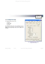
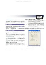
3.4.1 Serial Port
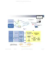
(Refer to Fig. 14 on previous page).
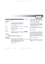
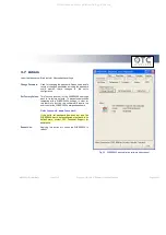
Serial Parameter
Baud rate:
for setting the baud rate of the WiSER2400’s serial
port. Supported values: 1200, 2400, 4800, 9600,
14400, 19200, 38400, 57600, and 115200 bps.
Default value:
9600 bps
Parity Bit:
for setting the error-checking bit. Supported values:
“None”, “Even”, and “Odd”
Data Bit:
for setting the number of bits in the data section.
Supported valued: 7 and 8.
Stop Bit:
supported value: 1.
Flow Control:
for setting local flow control option for the serial
connection. Supported modes: None, XON/XOFF
and Hardware flow control.
Serial Interface
The WiSER2400.IP supports RS-232 serial interface.
The WiSER2400.Plus supports RS-232/485/422 serial interfaces.
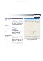
Data Packetizing
Start Frame Byte(s):
This value specifies a special character or characters
that signals the start of a data-string. Range from
0x00 to 0x1F and options of “None” and “Other”. If
“none” is selected, there would be no Start Frame
Byte. If “Other” is selected, the user can configure a
Start Frame Byte of up to six bytes.
Default value:
none
End Frame Byte:
This value specifies the character that signals the end
of a data-string, and the data would be sent to the
destination unit right after the radio receives the
designated character. Range 0x00 to 0x1F.
Default value:
0x0D = Carriage Return
If the user specifies ‘None’ (or leaves the field blank),
this will signify that there is no End Frame Byte and
data will be sent immediately once the WiSER2400
receives the next Start Frame Byte.
Max Bytes/Pkt:
This value specifies the maximum number of bytes
the WiSER2400 will hold before they are sent off.
Range: 1 to 200 bytes.
Default value:
200 bytes
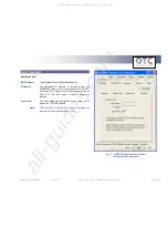
Serial Mode
Data Only Mode:
When this mode is activated, the WiSER2400 serial
port would accept only communication data traffic
and ignore the configuration command. This mode
will
stop
the
communication
between
the
administrative software and the WiSER2400. To re-
gain the access to the WiSER2400 for administration,
refer to the Troubleshooting Section for recovery
instructions.
Default value:
Data Only Mode
Data and Command Mode:
In this mode, the WiSER2400 serial port accepts both
communication data traffic and the administration
commands.
All manuals and user guides at all-guides.com