OTC Wireless 802.11 Wireless Serial Solutions WiSER2400.IP Technical Manual Download Page 19


WiSER 2400 Technical Manual 

Version 2.16 

Copyright 

 2001-2005, OTC Wireless, Inc. All Rights Reserved 

Page 19 of 32 


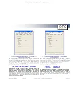
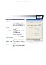
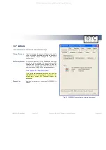
Fig. 10  Administrative software dialog with a PC connected to the 

WiSER2400 via a serial cable 


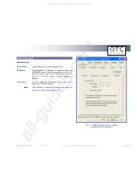
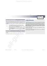
Fig. 11  Administrative software dialog with a PC connected to the 

WiSER2400 wirelessly. 

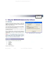
Fig. 10 shows the administrative program interface when the PC is connected 
with the WiSER2400 through the serial port by a cable. The user first needs to 
select the proper COM port on the PC and its baud rate, byte size, and parity 
(as  shown  in  the  top  of  Fig.  10)  to  match  those  of  the  WiSER2400  before 
clicking on the “Connect” button to establish communication link between the 
administrative program and the WiSER2400 unit.  


Defaults:

 Baud Rate: 9600 / Data bits: 8 / Parity: none 

 
Alternatively,  the  user  can  click  on  the  “Detect…”  button  (as  shown  in  the 
bottom  of  Fig.  10)  to  have  the  software  automatically  detect  the  RS232 
parameter settings of the WiSER2400 at a given COM port.  The connection 
between  the  PC  and  the  WiSER2400  will  be  automatically  made  when  the 
administrative software succeeds in correctly detecting the parameter settings 
of the WiSER2400. Once the connection is made, the Connect button will turn 
into a Disconnect button.  Simply click on the “Disconnect” to terminate the link 
between the PC and the WiSER2400. 

Fig. 11 shows the administrative program interface when the PC is wirelessly 
connected  to  the  WiSER2400.    To  connect  the  PC  to  the  WiSER2400  via 
wireless networking, one needs to make sure that the WiSER2400 and the PC 
running the administrative software are on the same subnet. 
 
The default IP settings for the WiSER2400 are: 


IP address:


192.168.11.191 

Subnet mask:


255.255.255.0


The  administrative  program,  when  started  in  the  wireless  connection  mode, 
will automatically scan for all the available WiSER2400 units on the network. 
Alternatively, the user can force a scan by clicking the “Get MAC/IP” button as 
shown in the top of Fig. 4b. The scan results will be displayed in a pull-down 
list.  The  user  then  selects  from  the  menu  for  the  unit  to  be  configured  or 
monitored. 

All manuals and user guides at all-guides.com

Summary of Contents for 802.11 Wireless Serial Solutions WiSER2400.IP

Page 1: ...TECHNICAL MANUAL For WiSER2400 IP WiSER2400 Plus 802 11 Wireless Serial Solutions http www otcwireless com All manuals and user guides at all guides com a l l g u i d e s c o m...

Page 2: ...r by any means electronic or mechanical for any purpose without the express written permission of the seller If however your only means of access is electronic permission to print one copy is hereby g...

Page 3: ...t redirector 9 2 WiSER Deployment Strategies 10 2 1 Using the WiSER2400 in a Point to point Link 10 2 2 Using the WiSER2400 in a Point to multiple point Link 14 3 Using the WiSER 2400 Administration S...

Page 4: ...ted to cash registers electronic whiteboards and navigational instruments Administration of the WiSER2400 is done through a Windows based administrative software program The administration software ca...

Page 5: ...ctor software VirCOM Model WiSER2400 IP WiSER2400 Plus Standard 802 11 and 802 11b Host Interface RS232 WiSER2400 IP RS232 485 422 WiSER2400 Plus Frequency 2 4GHz 2 497GHz RF Channels 11 channels US C...

Page 6: ...a device Two cables are included in the package The RS 232 P cable is for connecting the WiSER2400 IP to the RS232 port of DCE equipment whiteboard instrument etc during communication It terminates in...

Page 7: ...ting modes 1 1 5 Status LEDs Power on the WiSER2400 the LEDs on the front panel should exhibit the following patterns Refer to Fig 3 and Fig 4 LED Color Light Blinking Pattern Indication ON RED Steady...

Page 8: ...S 422 8 N C 9 V Up to 32 VDC 10 GROUND DB 9 male connector Pin 1 DCD 2 RXD 3 TXD 4 DTR 5 Ground 6 DSR 7 RTS 8 CTS 9 Dip Switch Location from left to right 1 RS232 485 selector 2 Full Half duplex selec...

Page 9: ...al A TCP IP wireless network that connects the PC running the administrative program and the WiSER2400 unit To support the WiSER2400 administrative software the computer must meet the following minimu...

Page 10: ...etc with that on the PC side for a TCP IP or UDP IP connection Configure the WiSER2400 to operate in the proper wireless network type Infrastructure mode for linking to an access point or Ad hoc mode...

Page 11: ...WiSER 2400 Technical Manual Version 2 16 Copyright 2001 2005 OTC Wireless Inc All Rights Reserved Page 11 of 32 Fig 5 All manuals and user guides at all guides com a l l g u i d e s c o m...

Page 12: ...y configure the serial parameters of the WiSER2400 on the PC side so that it can communicate with the PC Configure the WiSER2400s on either side of the link to match up their TCP UDP IP settings liste...

Page 13: ...WiSER 2400 Technical Manual Version 2 16 Copyright 2001 2005 OTC Wireless Inc All Rights Reserved Page 13 of 32 Fig 6 All manuals and user guides at all guides com...

Page 14: ...ate in UDP broadcast mode Enable each WiSER2400 to receive UDP broadcasts Configure the WiSER2400s to operate in the proper wireless network type Infrastructure mode for linking to an access point or...

Page 15: ...WiSER 2400 Technical Manual Version 2 16 Copyright 2001 2005 OTC Wireless Inc All Rights Reserved Page 15 of 32 Fig 7 All manuals and user guides at all guides com...

Page 16: ...e so that it can communicate with the PC Configure the WiSER2400s on either side of the link to match up their UDP IP settings listening port destination IP address etc for a UDP IP connection Enable...

Page 17: ...WiSER 2400 Technical Manual Version 2 16 Copyright 2001 2005 OTC Wireless Inc All Rights Reserved Page 17 of 32 Fig 8 All manuals and user guides at all guides com...

Page 18: ...window will pop up as shown on the right when the administrative program starts Once the connection selection is chosen the administrative program will display an interface as shown in Fig 10 and Fig...

Page 19: ...The connection between the PC and the WiSER2400 will be automatically made when the administrative software succeeds in correctly detecting the parameter settings of the WiSER2400 Once the connection...

Page 20: ...tion of a WiSER2400 a password must be submitted before the configuration command is executed After entering the password click OK to proceed Cancel to stop The Password Utility is also used to add or...

Page 21: ...ccess point the WiSER2400 is connected with or the group ID in an ad hoc peer to peer network the firmware version and release date role of the radio RF channel port status link quality and signal str...

Page 22: ...al Port Serial IP Proxy Wireless Port Peer Host After selecting the desired section click on the Refresh button at the bottom of the page to bring up the current settings After changing the settings u...

Page 23: ...the user can configure a Start Frame Byte of up to six bytes Default value none End Frame Byte This value specifies the character that signals the end of a data string and the data would be sent to th...

Page 24: ...ubnet mask settings Gateway For specifying the IP address of the Gateway Protocol TCP Client For setting the WiSER2400 as a TCP Client TCP Server For setting the WiSER2400 as a TCP Server UDP For sett...

Page 25: ...a peer to peer wireless network Default value Infrastructure Channel For setting the RF channel of the WiSER2400 when operated in the Ad Hoc mode Supported value 1 to 11 US 1 to 13 International Adva...

Page 26: ...s set to communicate with For TCP server and UDP modes the IP Address can be left as 0 0 0 0 In TCP client mode a valid IP address is required Listen Port The port number the destination device listen...

Page 27: ...s For automatic key generation select Pass phrase and enter an arbitrary combination of continuous alphanumerical characters into the Pass phrase field The maximum length allowed for the character str...

Page 28: ...om the serial COM port but were discarded by the WiSER2400 before being able to be transmitted out wirelessly usually due to buffer overflow 3 6 2 WLAN Statistics Transmitted Frames The total number o...

Page 29: ...s all of the WiSER2400 s settings back to its factory defaults To prevent unauthorized tampering with a WiSER2400 s settings in order for this feature to function the software will require the user to...

Page 30: ...should show the MAC address of the destination unit If this does not work check the IP address settings Poor Link Quality If the Signal Strength indicator is reasonably high 20 and the Link Quality is...

Page 31: ...SER2400 radio is established the user can start reconfiguring the WiSER2400 radio Technical Support If problems are still not resolved please contact our Technical Support to obtain further assistance...

Page 32: ...correct the interference by one or more of the following measures Relocate your WLAN equipped laptop computer Increase the separation between the WLAN equipped laptop computer and other electronics C...

Reviews: