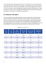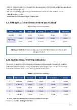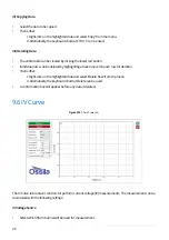
22
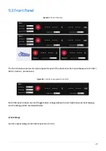
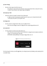
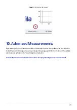
Figure 9.5.
Control and measurement for the Vsenses.
(II) Current Range
•
Sets the current range of the SMU to be used.
I. This defines the upper limit and sensitivity of current measurements that can be performed by
the SMU. These values for each range are given in
Table 6.4
.
(III) Samples per Point
•
Select the number of samples to be taken for each data point.
I. A higher number of samples per point will improve the accuracy of a measurement but will
increase the time taken for it to be performed.
(IV) Voltage Limit
•
Sets the maximum voltage that the SMU can source (default 10.5 V).
I. If the measured voltage is above the voltage limit, the output voltage will be set to 0 V.
(V) Current Limit
•
Sets the maximum current that the SMU will measure.
I. If the measured current is above the set current limit, the range will automatically be switched to
Range 1 to prevent damage to the SMU.
II. If the SMU is already at Range 1, the output voltage will be set to 0 V.
Each Vsense panel contains an on/off toggle button, the voltage measurement display, and the settings, which
are detailed below.

