Optical Scientific Inc
OFS 2000CW User’s Guide
P/N 1910-905
Rev. 03/28/13
48
7 Optical Alignment
(Continued)
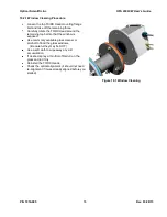
appropriate terminal strip locations (C1, C2 and Ground) on TB J2 on the Receiver board. DO NOT lift the wire
that is already in those locations but slip your wire in beside it and tighten the screw back down. The scale will
be different than on the controller display and will be approximately 0-2.5 volts. Regardless of the voltage
measured, you job is to maximize each of the A and B voltages through the aiming process, as described in
the previous paragraph.
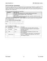
A useful exercise while aiming is to turn one of the adjustment knobs quite a number of turns in one direction
(say clockwise) until the general red illumination “spot” of red light on the receiver side moves so far out of
alignment that the detector board (and lenses) grow dark. At this point, stop turning and reverse the knob
rotation direction and bring the red spot back, completely over the detector (making it bright again) and
continue moving it until you make the detector board (and lenses) grow dark again. In doing this you will get a
feel for the speed of movement of the red spot. Practice this a couple of times and now it will be easier to bring
the spot back and center it on the detector board and have some confidence that it is properly centered. Do
this exercise with both the Up/Down and Side-to-Side adjustment knobs.
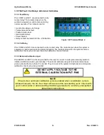
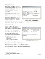
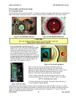
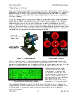
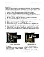
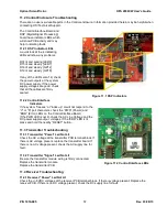
Figure 7.2 Transmitter Module
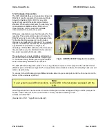
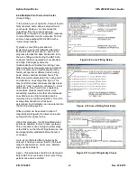
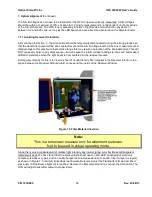
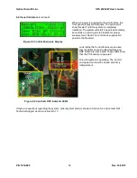
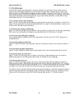
Figure 7.3 Beam Centering
In Figure 7.3
“Beam Centering”, the outer ring represents the general red illumination spot of light that has
been sent to the receiver side. The solid spot within the ring represents the detector window on the receiver
side (as seen from the transmitter side). In general the goal of the aiming process is to end up with the circular
detector board centered within the red spot of light that has been transmitted to the receiver side.
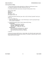
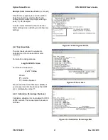
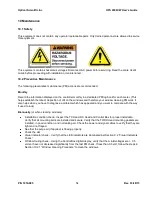
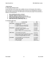
Observe the A and B signal voltage
readings on the control panel display.
These represent the amount of light
reaching the A and B detectors on the
receiver board using a scale of 0-10 volts.
These may shift up and down slightly
according to variations in air flow between
the transmitter and receiver.
Note:
These values do not have to be
identical for the OFS to operate correctly.
If you have followed the steps in Section 6.1
“Transmitter Setup”, the alignment should be very good and
voltage values may be at or around 7.00 (or lower) but a maximum value for your particular installation. If you
are still unsure that the aim is correct, repeat the aiming procedure in the transmitter set-up section.
Continued on next page
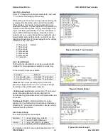
Figure 7.4 Front Panel Display (example)
BOTTOM KNOB
Horizontal adjustment
[LEFT - RIGHT]
TOP KNOB
Vertical adjustment
[HIGH - LOW]

