Optical Scientific Inc
OFS 2000CW User’s Guide
P/N 1910-905
Rev. 03/28/13
45
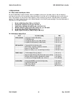
Reflective
Arrow
6 Transmitter and Receiver Setup
6.1 Transmitter Setup
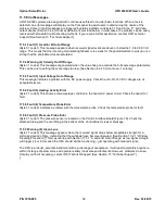
The Transmitter uses an eye-safe red LED.
1
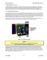
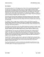
The Receiver module is equipped with reflectors to aid in sighting.
Note: Under certain operating conditions, it may be difficult to see the reflection from the receiver module.
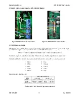
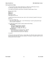
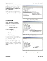
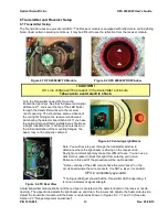
Figure 6.1 OFS 2000CW TX Module
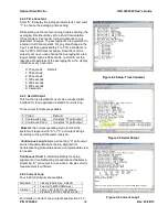
Figure 6.2 OFS 2000CW RX Window
! CAUTION !
AC Line voltage will be present in the transmitter enclosure.
Take care to avoid electric shock.
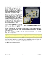
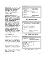
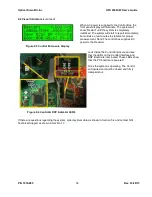
Turn the Transmitter power ON. Open the
transmitter rear door. See that the power and signal
LEDs are lit
2
. Look over the top of the LED barrel
through the transmitter window to the receiver
nozzle opening. You should see some evidence of
the red light shining on the receiver window and
illuminating the detector board behind it. If you have
the optional target reflector installed you should see
a bright reflection from it. Although care is taken in
the initial installation of the mounting flanges, the
beam may not be properly centered.
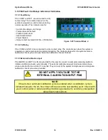
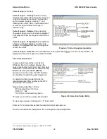
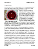
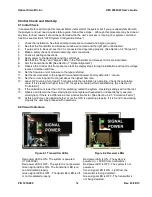
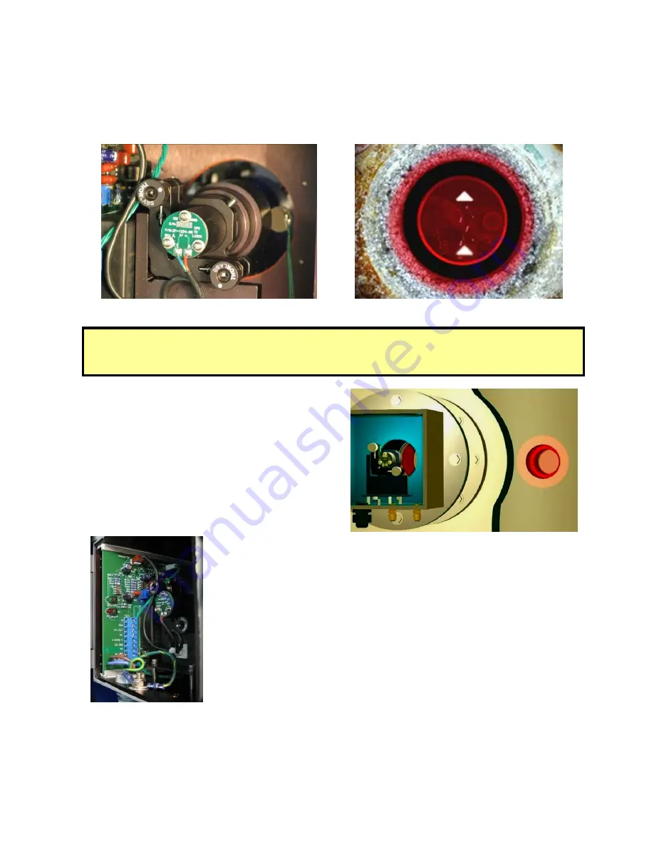
Figure 6.3 Centering Light Beam
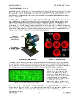
Figure 6.4 TX Rear View
Note: You will have to peer through the transmitter window to
determine where the light beam is striking on the receiver side.
Daylight or ambient light may make this difficult to see. You can use a
dark cloth or jacket to block this light from entering your vision.
Patience in this part of the procedure will be well rewarded.
1
Some versions of the LED module have the word “Laser” on the
circuit board where the wire connects. It is NOT a laser, it is an LED.
OFS is completely eye-safe.
2
The Signal LED just shows that the Transmitter LED is operating. It
is not an indicator of signal strength.
Adjust transmitter module knobs until the red spot is centered on the detector board in the receiver nozzle
opening. The upper knob adjusts the light beam up and down, the lower knob adjusts the beam side-to-side.
Adjust the transmitter module until the beam is centered as shown in Figures 6.3, 7.1 and 7.3. [See also
Section 2.3
“Flange Alignment Guidelines”].

