Optical Scientific Inc
OFS 2000CW User’s Guide
P/N 1910-905
Rev. 03/28/13
16
2.6 Flange Pipe Mounting
Air infiltration through improperly sealed
flanges or from double walled stacks with
dead space between the inner and outer
walls may cause incorrect velocity readings.
Be sure that there are no openings for air to
leak into (or out of) (except for purge air
where necessary) Figures 2.5 & 2.6
illustrate the incorrect and correct methods
of installing the OFS.
Insure that the mounting pipe (nozzle) is
well sealed to the stack.
Dead space between double-walled or
stacks equipped with interior liners must be
bridged.
All gaskets and seals must be tight.
Note
– These precautions do not apply to
purge air, which is nominally under the
user’s control. Proper use of purge air is
discussed in Section 3.4
“Purge Air”.
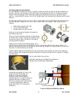
Figure 2.5 Flange Installation - Incorrect
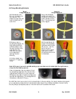
Figure 2.6 Flange Installation - Correct
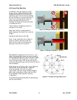
OFS 2000CW is designed to mount to the 4
– inch
ANSI 150# pipe flanges commonly used in industry.
The standard dimensions are shown at right in Figure
2.7.
Note that the OSI convention is to have a bolt
hole at top dead center. (The people mounting the
nozzle and flange will have to know this before they do
their installation)
While this type is commonly used, it is not exclusive.
Flare stacks, chemical processes, hazardous
environments each have heir own unique
requirements. OSI has a range of flange adapters,
gate valves, sight glasses, spray rings, and other
items available to cope with any mounting
configuration.
Contact OSI Engineering Department regarding any
special considerations.
Figure 2.7 Common Flange Dimensions


