background image

INSTALLATION MANUAL / USER MANUAL

REMOTE CONTROL PANEL RC102

PAGE: 4

JUL 18/2022

© 2022 Orolia S.A.S. All rights are strictly reserved. 

4. RCP installation

A. Installation recommendations

IMPORTANT: Installation of this RCP is covered by Service Bulletin 
"SB S1820513-25-02": 

Refer to Section 1. Introduction, page 1

.

The RCP shall be installed in the cockpit. The RCP shall be readily 
accessible from the pilot’s normal seated position.

CAUTION: RC102 RCP may only be installed with KANNAD 406 AF 
COMPACT P/N S1840501-01 at amendment M or higher or on 
KANNAD 406 AF COMPACT ER P/N S1840501-04. A WARNING label 
is supplied with the kit and must be stuck on the 2-wire bundle on the 
ELT side.

2 types of front plates may be installed. Choose the appropriate front plate 
according to the aircraft’s instrument panel. 
Connection of RC102 requires a 2-wire bundle. A pin-to-pin wiring has to 
be provided by the installer with AWG24 wires. Shielded wires are 
recommended.
The wires are soldered to a PCB installed on the switch. This operation can 
be carried out before installation.
On the ELT side, the wires are soldered to a 12-pin plug that can be either 
a standard "DIN12 connector" (P/N S1820514-03) or a connector with an 
integrated serial memory module called "Programming Dongle" 
(P/N S1820514-01).

B. RCP Installation procedure

(1) Mount RCP

(

Refer to Figure 3: RCP mounting diagram

)

NOTE: Legs of LED must be protected by heat shrinkable sleeves.

Choose one of the front plates (1a or 1b) according to the space 
available on the instrument panel.
Front plate (1a)
• Place the front plate (1a) on the instrument panel and use it as drilling 

mask or;

• Trace the centers of the two holes according to drilling mask supplied;
• Drill a hole Ø 8 mm for the LED mounting (2) (top of the panel);
• Drill a hole Ø6.5 mm for the switch (3b) (bottom of the panel);

Note: the switch (3b) is already soldered to a PCB (3a)

• Tear off protection of front plate (1a) from self-adhesive film;

Summary of Contents for RC102

Page 1: ...09005E Date of rev JUL 18 2022 Revision 04 First Issue MAR 02 2009 Orolia S A S INSTALLATION MANUAL USER MANUAL P N S1820513 21 2022 Orolia S A S All rights are strictly reserved REMOTE CONTROL PANEL RC102 ...

Page 2: ...CTLY RESERVED THIS DOCUMENT AND ANY ATTACHED MATERIALS CONTAINS PROPRIETARY AND CONFIDENTIAL INFORMATION AND DATA AND IS THE SOLE PROPERTY OF OROLIA S A S THE DOCUMENTS ANY ATTACHED MATERIALS AND OR INFORMATION CONTAINED THEREIN MUST NOT BE USED DISSEMINATED OR DISTRIBUTED EXCEPT FOR THE AGREED PURPOSE UNAUTHORIZED USE REPRODUCTION OR ISSUE TO ANY THIRD PARTY IS NOT PERMITTED WITHOUT THE PRIOR WRI...

Page 3: ...ation procedure 4 Mount RCP 4 Connection of RCP bundle to ELT 7 Working mode 8 Controls 8 Working mode information 9 Remote control 9 Monitoring 9 Operation 10 Stand by mode 11 ON mode 11 RESET TEST 11 Self test 11 RESET 12 RCP operational tests 12 Technical characteristics and compatibility 14 Technical characteristics 14 Environmental characteristics 14 Electrical characteristics 14 Compatibilit...

Page 4: ...lowing address Orolia S A S Z I des Cinq Chemins CS10028 Kannad Aviation 56520 GUIDEL FRANCE Web https www orolia com support Tel 33 0 2 97 02 49 00 2 KANNAD ELTs System Presentation KANNAD ELTs system is composed of 1 an ELT transmitter Refer to B Compatibility list page 14 and its mounting bracket 2 a remote control panel 3 a DIN 12 connector P N S1820514 03 or programming dongle P N S1820514 01...

Page 5: ...patible with KANNAD406 AF COMPACT series ELTs It is specially intended for general aviation or helicopters and can also be adapted for cabin installations or retrofits on board airliners thanks to its small dimensions The 102 enables remote control of the primary functions of KANNAD ELTs Manual activation Reset andTest as well as visual monitoring CAUTION RC102 is not compatible with KANNAD 406 AF...

Page 6: ... with white markings 2 a red LED annunciator a led stand a led mounting washers and nuts 3 a PCB on which is soldered a 3 position toggle switch with 2 locked positions and a momentary position plus its washer and nut 4 an identification label 5 a CAUTION label Figure 2 RC102 Remote Control Panel Kit These components are delivered in a kit and must be assembled then directly mounted on the aircraf...

Page 7: ...wiring has to be provided by the installer with AWG24 wires Shielded wires are recommended The wires are soldered to a PCB installed on the switch This operation can be carried out before installation On the ELT side the wires are soldered to a 12 pin plug that can be either a standard DIN12 connector P N S1820514 03 or a connector with an integrated serial memory module called Programming Dongle ...

Page 8: ...nel 1b on to the instrument panel and use it as drilling mask or Trace the centers of the two holes according to drilling mask supplied Drill a hole Ø 8 mm for the LED mounting 2 left of the panel Drill a hole Ø6 5 mm for the switch 3b right of the panel Note the switch 3b is already soldered to a PCB 3a Drill 4 holes of Ø 3 mm for the screws used to fix the RCP Screw the front plate 1b onto the i...

Page 9: ...INSTALLATION MANUAL USER MANUAL REMOTE CONTROL PANEL RC102 PAGE 6 JUL 18 2022 2022 Orolia S A S All rights are strictly reserved Figure 3 RCP mounting diagram ...

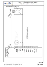
Page 10: ... S1840501 01 at amendment equal or higher than M or to any KANNAD 406 AF COMPACT ER P N S1840501 04 Solder the DIN12 connector or Programming Dongle on the other side of the bundle pins K and M Connect the wire from M of PCB 3a to pin M of DIN12 connector Connect the wire from K of PCB 3a to pin K of DIN12 connector Stuck the CAUTION label 5 on the cable bundle close to the DIN12 connector Perform...

Page 11: ...1 a 3 position switch ON ARMED RESET TEST 2 a red or white visual indicator Figure 5 RCP controls The visual indicator gives an indication on the working mode of the ELT After the self test one long flash indicates that the system is operational and that no error were found a series of short flash indicates the test has failed In operation mode periodic flashes during 121 5 transmissions long flas...

Page 12: ... an emergency the switch must stay in this position 3 RESET TEST is used either to stop the ELT transmission if activated or to perform a self test Figure 6 3 position switch The OFF mode is not available on the remote control panel but directly on the ELT itself by switching it in OFF position Important notice TEST RESET downwards is a momentary position Refer to operation manual of the ELT for p...

Page 13: ...ictly reserved Figure 7 Monitoring Refer to operation manuals of the ELTs for precise information on these modes 6 Operation Figure 8 Operating modes Visual indicator STAND BY ON RESET TEST Pull and lift upwards Press downwards at least 1 s then release Press downwards at least 1 s then release Pull and lift upwards ...

Page 14: ...TEST This mode is used either to perform a self test or to stop the ELT transmission if activated 1 Self test IMPORTANT Do not perform self test without the antenna connected Self test must be performed regularly by a pilot or maintenance personnel from the Remote Control Panel but should not be done more than specified in the ELT user manual However each self test consumes energy from the battery...

Page 15: ...ator of RCP is flashing in the same way than the one of the ELT Press the switch downwards for at least 1 second then release it the switch comes back in ARMED position the ELT comes back in stand by mode D RCP operational tests Check correct operation of RCP visual indicator by switching ELT and RCP as described in the following sequential procedure Figure 9 RCP visual indicator operation with EL...

Page 16: ...INSTALLATION MANUAL USER MANUAL REMOTE CONTROL PANEL RC102 PAGE 13 JUL 18 2022 2022 Orolia S A S All rights are strictly reserved Figure 9 RCP visual indicator operation ...

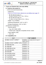
Page 17: ... x 1 38 in Weight 13 g 0 028lbs Operating temperatures 20 C to 55 C Storage temperatures 55 C to 85 C 2 Electrical characteristics 3 position switch Type ON MOM ARM Contact type Gold plate compatible with low current Visual indicator LED Color red B Compatibility list ELT PART NUMBER KANNAD 406 AF COMPACT S1840501 01 at amendment equal or higher than M KANNAD 406 AF COMPACT ER S1840501 04 AP INTEG...

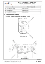
Page 18: ...NEL RC102 PAGE 15 JUL 18 2022 2022 Orolia S A S All rights are strictly reserved 8 Schematics and diagrams A RC102 Outline dimensions and drilling mask AP H INTEGRA ER S1854501 01 AP H INTEGRA S1854501 02 AP H INTEGRA ER N S1854501 03 ELT PART NUMBER ...

Page 19: ...INSTALLATION MANUAL USER MANUAL REMOTE CONTROL PANEL RC102 PAGE 16 JUL 18 2022 2022 Orolia S A S All rights are strictly reserved B RC102 Wiring diagram ...

Page 20: ...22 Orolia S A S All rights are strictly reserved DOC09005E Distributed by Manufactured by Orolia S A S Z I des Cinq Chemins CS10028 56520 GUIDEL FRANCE Phone 33 0 2 97 02 49 49 Website https www orolia com ...

Reviews: