MW1008P, user manual
36
Procedure for changing the values of resistors
The display shows «
RCALX
:XXXXXX Ω
». Press the
n/Vs/M
(choice EDIT) to edit the
value. A cursor appears under the first digit to the left. The number can be incremented by
pressing the
n/Vs/M
or decremented by pressing MENU.
The cursor position can be changed by pressing the
L/C/R
(rightward shift) or by pressing
MODEL
(leftward shift). Accept the value by pressing the button under OK.
The first step of the calibration set is now complete. It remains for us to proceed with the
calibration itself.
CALIBRATION
Prior to calibration the first step described above must be completed in its entirety. The
calibration procedure involves several steps which must be realized in order. From the menu
"PARAM CAL EXIT"
:
1)
Press the
n/Vs/M
(choice CAL). The
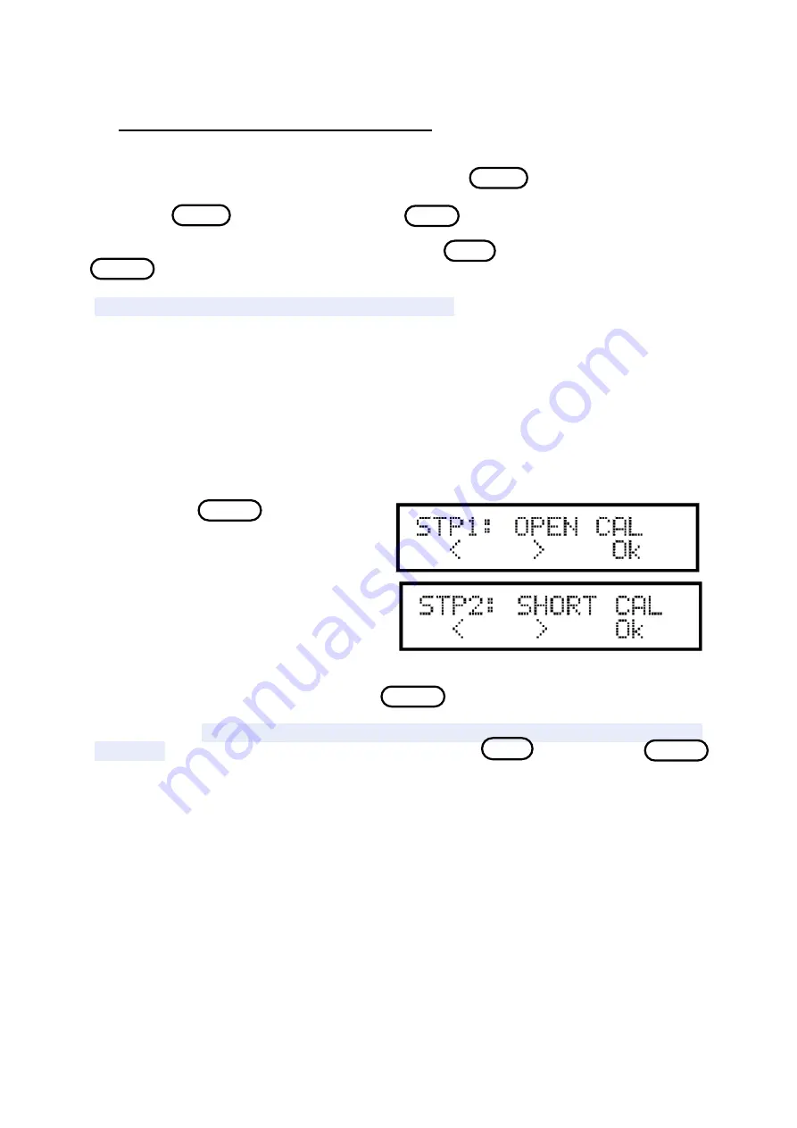
instrument displays the following screen.
The instrument will conduct an open circuit
calibration. The instrument will use this
calibration to compensate for the parasitic
elements in the calibration of resistance. It is
therefore necessary to maintain the same
position of cables for the following steps in
order not to change the value of these
parasitics. If you use cable MW10 mini-pincers LD and LS should be connected together as
well as mini-pincers HD and HS. Press the
n/Vs/M
(choice "Ok"). The instrument displays
"Opening 100 Hz" and a progress bar on the second line. The device makes a measurement at
each frequency. When the instrument has completed this step it will automatically go to the
next step. It is possible to choose a particular step by the
L/C/R
( choice < ) and
n/Vs/M
(choice >). It is possible to perform the steps STP3 to STP8 in any order, but the calibrations
"OPEN" and "SHORT" must always be conducted first.
2)
The instrument displays the following screen for calibrating short-circuit. Short the
mini-pincer with a piece of thick wire. Choose the option Ok Similarly for calibrating
"OPEN" the instrument performs a calibration at all frequencies and then passes to the next
step. If the instrument displays "FAIL" at the end of the first calibration at 100 Hz verify that
the test clips are short circuited, then repeat.
3)
The instrument will now carry out the calibration of impedance for each of the ranges
and at all frequencies. There are six steps STP3 to STP8 where you should connect the
calibrating resistors supplied with the kit and whose values have been previously programmed


