


IG-284-EN version 03; 06/05/2020
48
Recommended sequence
of operations
General Instructions
cgm
.800: Medium-voltage switchgear with integrated insulation in SF
6
gas
up to 36 kV in accordance with IEC Standard with rated current up to 800 A
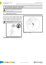
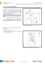
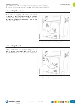
5.6. Fuse replacement sequence
To access the fuse holders, fi rst remove the cable
compartment cover. It is essential to close the earthing
switch. If any of the three fuses blows, the switch-
disconnector (a) will open automatically; this is indicated
by the red position indicator (b) located on the front of the
driving mechanism compartment.
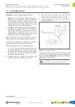
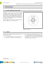
As an option, an auxiliary blown fuse indication for
any of the three fuses is also available. More precisely,
it consists of a normally open contact and a normally
closed contact (1NO + 1NC) for auxiliary circuits, such
as an illuminated indication showing that any of the
fuses has blown.
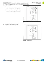
Figure 5.28.
Fuse blow trip indication
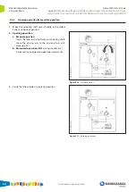
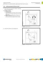
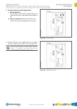
In order to replace the fuses, the following procedures must
be followed:
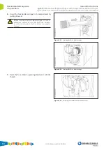
1.
Close the earthing switch (c).
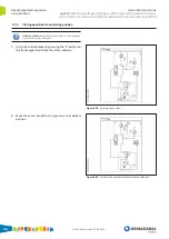
2.
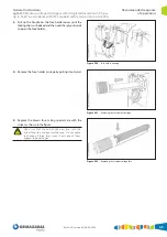
Remove the cable and fuse compartment access cover
by pulling the handle (d) up.
Figure 5.29.
Cable and fuse compartment cover opening
Summary of Contents for velatia cgm.800
Page 71: ......


