


IG-284-EN version 03; 06/05/2020
3
General Instructions
cgm
.800: Medium-voltage switchgear with integrated insulation in SF
6
gas
up to 36 kV in accordance with IEC Standard with rated current up to 800 A
Contents
Contents
1. General description ...................................................4
1.1.
Models . . . . . . . . . . . . . . . . . . . . . . . . . . . . . . . . . . . . . .4
1.2.
Standards applied. . . . . . . . . . . . . . . . . . . . . . . . . . . .4
1.3.
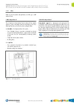
Main components . . . . . . . . . . . . . . . . . . . . . . . . . . .5
1.3.1. Gas tank . . . . . . . . . . . . . . . . . . . . . . . . . . . . . . . . . . . . .6
1.3.2. Driving mechanism compartment . . . . . . . . . . . .6
1.3.3. Base . . . . . . . . . . . . . . . . . . . . . . . . . . . . . . . . . . . . . . . . .7
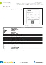
1.3.4. Name plate . . . . . . . . . . . . . . . . . . . . . . . . . . . . . . . . . .8
1.4.
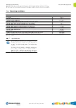
Characteristics table . . . . . . . . . . . . . . . . . . . . . . . . .9
1.5.
Dimensions and weights . . . . . . . . . . . . . . . . . . . .10
1.6.
Operating conditions . . . . . . . . . . . . . . . . . . . . . . .11
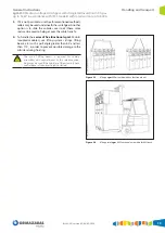
2. Handling and transport ...........................................12
2.1.
Lifting means . . . . . . . . . . . . . . . . . . . . . . . . . . . . . . .12
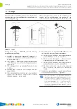
3. Storage ......................................................................14
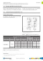
4. Installation ...............................................................15
4.1.
Unpacking the equipment . . . . . . . . . . . . . . . . . .15
4.2.
Location of accessories during transport . . . . .15
4.3.
Minimum installation distances. . . . . . . . . . . . . .16
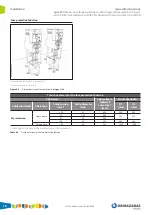
4.4.
Recommended cable connection trenches. . .17
4.4.1. Cubicles with internal arc in tank up to
20 kA - 0.5 s . . . . . . . . . . . . . . . . . . . . . . . . . . . . . . . . .17
4.4.2. Cubicles with classification of internal arc
IAC up to 25 kA - 1 s . . . . . . . . . . . . . . . . . . . . . . . . .20
4.5.
Fastening to the floor . . . . . . . . . . . . . . . . . . . . . . .24
4.5.1. Fastening to the floor on profile . . . . . . . . . . . . .24
4.5.2. Fastening to the floor by anchoring. . . . . . . . . .25
4.6.
Connecting the cubicles. . . . . . . . . . . . . . . . . . . . .28
4.7.
Earthing the switchgear . . . . . . . . . . . . . . . . . . . . .28
4.8.
Cable connections . . . . . . . . . . . . . . . . . . . . . . . . . .29
4.8.1. Horizontal front connection . . . . . . . . . . . . . . . .30
4.8.2. Cable connection in fuse protection
function 1400 mm high . . . . . . . . . . . . . . . . . . . . .32
5. Recommended sequence of operations .................34
5.1.
Checking the gas pressure . . . . . . . . . . . . . . . . . .34
5.2.
Live voltage indicator . . . . . . . . . . . . . . . . . . . . . . .35
5.3.
Phase concordance check . . . . . . . . . . . . . . . . . . .36
5.4.
Feeder function. . . . . . . . . . . . . . . . . . . . . . . . . . . . .37
5.4.1. Mimic diagram. . . . . . . . . . . . . . . . . . . . . . . . . . . . . .37
5.4.2. Actuating levers . . . . . . . . . . . . . . . . . . . . . . . . . . . .37
5.4.3. Opening operation from earthing position. . .38
5.4.4. Switch closing operation from open
position . . . . . . . . . . . . . . . . . . . . . . . . . . . . . . . . . . . .39
5.4.5. Opening operation from closed position. . . . .40
5.4.6. Earthing operation from the open position . .41
5.4.7. Cable test. . . . . . . . . . . . . . . . . . . . . . . . . . . . . . . . . . .42
5.5.
Fuse protection function . . . . . . . . . . . . . . . . . . . .43
5.5.1. Mimic diagram. . . . . . . . . . . . . . . . . . . . . . . . . . . . . .43
5.5.2. Actuating lever . . . . . . . . . . . . . . . . . . . . . . . . . . . . .43
5.5.3. Opening operation from earthing position . .44
5.5.4. Spring charge operation and closing of the
switch-disconnector from isolating position .45
5.5.5. Opening operation from switch-disconnector
closed position . . . . . . . . . . . . . . . . . . . . . . . . . . . . .46
5.5.6. Earthing operation from open position . . . . . .47
5.6.
Fuse replacement sequence . . . . . . . . . . . . . . . . .48
5.6.1. Selection of recommended fuses . . . . . . . . . . . .52
5.7.
Circuit-breaker function with AV/RAV
driving mechanism . . . . . . . . . . . . . . . . . . . . . . . . .53
5.7.1. Mimic diagram. . . . . . . . . . . . . . . . . . . . . . . . . . . . . .53
5.7.2. Spring charge and actuating levers . . . . . . . . . .54
5.7.3. Opening operation from earthing position. . .54
5.7.4. Closing operation from isolating position . . .56
5.7.5. Opening operation from closed position. . . . .58
5.7.6. Earthing operation from open position . . . . . .60
6. Safety elements ........................................................62
6.1.
Acoustic earthing prevention alarm . . . . . . . . .62
6.2.
Interlocks . . . . . . . . . . . . . . . . . . . . . . . . . . . . . . . . . . .62
6.2.1. Locking with a padlock. . . . . . . . . . . . . . . . . . . . . .63
6.2.2. Locking with a lock. . . . . . . . . . . . . . . . . . . . . . . . . .63
7. Maintenance .............................................................64
7.1.
Live voltage indicator test . . . . . . . . . . . . . . . . . . .64
7.2.
Acoustic earthing prevention alarm test . . . . .65
7.3.
Specific maintenance for the
cgm
.800-v
cubicle . . . . . . . . . . . . . . . . . . . . . . . . . . . . . . . . . . . . .66
8. Spares and accessories ............................................67
9. Environmental information ....................................69
Summary of Contents for velatia cgm.800
Page 71: ......