background image

System manual

SM0974113 A 01

7

Figure 4

Figure 5

Figure 6

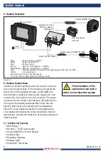
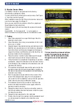
6. Monitor Service Menu

The SideEye monitor is programmed in the factory.

All necessary settings are made.

You can check this by entering the service menu. See Figure

4, 5 and the monitor manual.)

After installation open the info Page in the service menu and

scroll to the last page. See Figure 6.

Here you can check the connection of the Turn signal and

Speed signal during a test drive.

Check the speed. (should be almost the same as the tacho-

meter.)

Check AUX1   0= Turn signal off     C= turn signal on

After this follow the test procedure for the detection zones.

7. Testing

1.

Move the equipment to an open field larger than the

detection zone to test.

2.

Clean the sensor face of any accumulation of dirt, mud,

snow, ice, or debris.

3.

Visually inspect the attached wiring and cable and verify

that they are properly secured, not chafing or dangling

free where they could become snagged and damaged.

Inspect the Sensor and Monitor and verify that they are

securely attached to the equipment.

4.

Place the sensor in active mode. Make sure the equip-

ment has been secured and remains stationary.

5.

Verify the sensor is operational. Depending on operator

notification. Assure the detection zone has been cleared

of all obstacles. Any obstacles in the detection zone will

interfere with the test.

6.

The assistant should walk towards the sensor while the

operator notes when the warning activates, signifying

the sensor has detected the assistant and identifying the

detection zone limits.

7.

Next, the assistant should walk from the center of the

sensor field straight back, away from the equipment

(the center line of the detection zone) while the operator

notes when the warning (notification) stops.

8.

The assistant should move a meter to the left of the

sensor and walk towards the sensor again while the

operator notes the warning.

9.

Repeat the above step by moving out another meter to

the left and walking towards the sensor while the opera-

tor notes the warning.

10. Repeat this test sequence for the right side.

11. Finally, after the test, the operator and the assistant need

to communicate the details on the detection zone.

This test should be performed with two 

people, the operator who remains in 

the cab, and the assistant who walks 

through the sensor field (detection 

zone).

Summary of Contents for 0403130

Page 1: ...SRD Interface Box SideEye Set A System manual No SM0974113 A 01 Art No 0403130 8 2020 English SideEye Set A...

Page 2: ...quality management system IATF 16949 quality automotive ISO 14001 environmental management systems where applicable Safety In order to guarantee safe operation these safety instructions must be read...

Page 3: ...e radar The sensor transmits and receives low power narrow band 24 GHz radar signals It then processes the returned signals to determine if an object has reflected any energy back to the sensor and de...

Page 4: ...r mounting location is important for proper system operation The sensor should be mounted on the side of the vehicle with the bottom of the radar no lower than 600 mm and the top of the radar no more...

Page 5: ...he vehicle to an open space larger than the system detection zone to test The equipment ignition must be en ergized to power up the system Activate the system Check if there are no moving objects in t...

Page 6: ...e the vehicle s ignition power and connect to the red wire on the body harness If it is necessary to extend the power wire on the supplied harness use 20 AWG wire as a minimum Locate the vehicle s tur...

Page 7: ...active mode Make sure the equip ment has been secured and remains stationary 5 Verify the sensor is operational Depending on operator notification Assure the detection zone has been cleared of all ob...

Page 8: ...of the field of vision The monitor must be placed in such a way that the field of vision of surrounding traffic and the work area is obstruct ed as little as possible Obstruction of the operation The...

Page 9: ...20 15 0 30 1 5 3 0 Good Good Moderate Moderate Bad Bad Moderate incidental 0 40 Bad Good Bad continual 40 cm 75 cm 150 cm Moderate Bad Bad Good Bad Good Moderate 0 15 30 Bad Good Moderate 0 10 20 15 0...

Page 10: ...System manual 10 SM0974113 A 01 108 63 5 5 6 x 4 Units in mm Scale 1 1 TOP side 10 Drilling template...

Page 11: ...system become inoperative it could jeopardize the safety or lives of those who depend on the system 5 The SideEye System is intended for commercial use Proper installation of the object detection sys...

Page 12: ...entire units 14 General terms and conditions Orlaco Products BV is not liable for damage resulting from inadequate servicing incorrect usage or alterations made to the equipment without informing the...

Page 13: ...System manual SM0974113 A 01 13 15 Version details Version A 01 First issue August 2020...

Page 14: ...te our design manufacturing ware housing and service department Vision is our mission Orlaco therefore deploys the development manu facture supply and service of camera and display systems that will i...

Reviews: