


System manual
6
SM0974113 A 01
Power
Monitor RLED 7”
Camera FAMOS 118°
Red
= Power input 18...30V/DC
White
= Power input GND 0V
Blue
= Reverse signal
Brown
= Cam No. 2 activated at 7...30V/DC
White/Yellow = Cam No. 3 activated at 7...30V/DC
Grey
= Tachograph input, connected to the speedsignal of the truck. 4P/P/M
Yellow
= Turn signal input
Connect the grey wire to the tachograph;
This is the output speed signal for pulses per meter.
SRD sensor
Interface Box with
External speaker
CAN Radar
External speaker
with LED
Cable 10m M12 Green
Cable 10m M12 Green
Adapter cable SRD M12M-D8M
Camera FAMOS 118°
Red
= Power input 18...30V/DC
White
= Power input GND 0V
Blue
= Reverse signal
Brown
= Cam No. 2 activated at 7...30V/DC
White/Yellow = Cam No. 3 activated at 7...30V/DC
Grey
= Tachograph input, connected to the speed signal of the truck. 4P/P/M
Yellow
= Turn signal input
Connect the grey wire to the tachograph;
This is the output speed signal for pulses per meter.
SRD sensor
Adapter cable SRD M12M-D8M
SRD POWER MON SPEAKER CAM
Power
SRD Interface Box
“Side Assist”
External speaker
with LED
Optional; Not in the Set
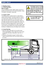
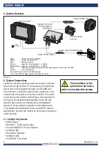
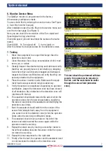
5. System Connections
Locate the vehicle’s ignition power and connect to the red
wire on the body harness. If it is necessary to extend the
power wire on the supplied harness, use 20 AWG wire
as a minimum. Locate the vehicle’s turn signal wire; only
connect this to the yellow wire of the monitor. The sensor
is powered by the monitor and interface. (Be sure that the
turn signal wire selected activates ONLY when the turn
signal is active and is the operational (not diagnostic)
signal. On some trucks the daytime running lights and/
or air brakes will activate the wires connected to the turn
signal lamp). Connect the white wire of the body harness to
vehicle ground.
5.1. SideEye Set Contents
•
SRD Sensor “”
•
Monitor 7” RLED with bracket
•
Camera FAMOS 118° with bracket
•
Interface Box
•
Mounting Hardware
•
Adapter cable
•
Cable M12 10m Green
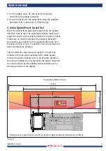
Figure 3
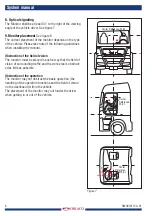
4. System Overview
The installation of the
system must not have a
switch to shut down the system.


