11
Preparation and Confirmation
Gauge
&
Controller / Piping
KRF110
Be sure to install the gauge according to following procedure.
※
For the controller installation position, refer to the outer dimension drawing provided on P29-31.
※
Do not apply a sealing tape when installing the pressure gauge. (Do not overtighten.)
※
Do not apply a sealing tape on the threads. After tightening the controller hand-tight, give an
additional quarter to half turn using a tool. Smooth surface due to application of a sealing tape
may result in excessively tightening the controller. This may damage or deform the thread part and
cause malfunction. (There is no need of securing high airtightness using a sealing tape or adhesive
agent because the pump is designed for low pressure/vacuum.)
※
Compound gauge is a part that is weak against impacts. Do not hit or drop the product with
compound gauge.
Piping
1.Avoid direct connection with steel pipe.
・
Use hose for inlet and exhaust piping. In case of direct connection with steel pipe, resonance with
the piping system
may cause noise or vibration.
For exhaust piping, use heat resistant and
pressure resistant (100kPa or over) hose.
・
Completely remove dirt and dust inside the hose before piping.
2.When intake air contains a big amount of dust, or if dust grains are very fine (10
μ
m or less), use
an appropriate filter in addition to the accessory filter.
3.Install the hose of the exhaust piping system properly in order to prevent condensed water
inside the system from entering the pump, and from discharging from the piping end.
If condensed water in the piping system enters the pump, the pump inside may be locked by rust or the
blades may not come out. To avoid this situation, take the following measures:
①
Install the valve or drain in the exhaust piping system
so that the condensation of water occurred inside the
system can drain out. Also, drain out the collected
condensation of water periodically. (See Figure 1.)
・
Provide valve or drain hose on the pump side in order
to prevent condensed water from entering into the pump.
・
In case of a long piping system, provide valve or drain
hose in the halfway of the system.
・
When condensed water discharges from the piping
end, install a valve or drain hose at the piping end.
②
If the pump is not frequently used, idle the pump for 10 to 15 minutes after finishing
operation.
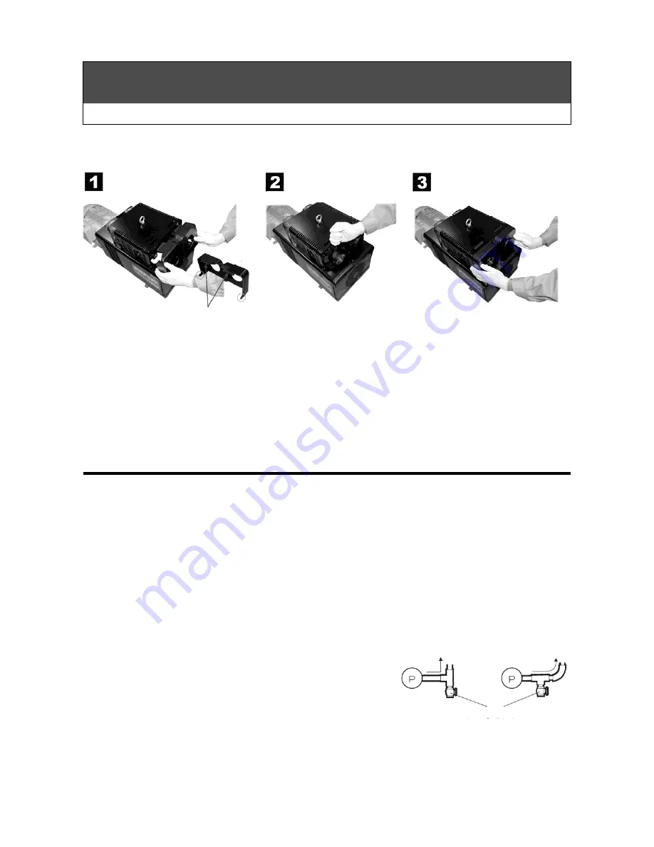
Remove the cover.
Install the gauge.
Push the check point, remove the claw and pull the case foward.
Claw
Press it back in place until
the cover claw is locked.
(Figure 1)
Piping end side
Piping end side
Drain or valve
Summary of Contents for KRF110
Page 28: ...26 Dimensional Outline Drawing KRF70 V 01 04 KRF70 VH 01 04 unit mm...
Page 29: ...27 Dimensional Outline Drawing KRF70 B 01 04 KRF70 BH 01 04 unit mm...
Page 30: ...28 Dimensional Outline Drawing KRF70 VB 01 04 KRF70 VBH 01 04 unit mm...
Page 31: ...29 Dimensional Outline Drawing KRF110 V 01 04 unit mm...
Page 32: ...30 Dimensional Outline Drawing KRF110 B 01 04 unit mm...
Page 33: ...31 Dimensional Outline Drawing KRF110 VB 01 04 unit mm...
Page 34: ...37 memo...
Page 35: ...37 memo...
Page 36: ...K No 0322 12 2 1 C DG TY...


