background image

on the outside of the tripod legs. Secure the wing nuts fin-
ger-tight.

2. Install and tighten the leg lock knobs on the bottom braces

of the tripod legs. For now, keep the legs at their shortest
(fully retracted) length; you can extend them to a more
desirable length later, after the tripod is completely assem-
bled.

3. Stand the tripod and mount upright and spread the tripod

legs apart as far as they will go, until the bracket is taut.
Connect the accessory tray to the accessory tray bracket
with the three wing screws already installed in the tray. Do
this by pushing the wing screws up through the holes in
the accessory tray bracket and threading them into the
holes in the accessory tray.

4. Next, tighten the screws at the tops of the tripod legs, so

the legs are securely fastened to the mount. Use the
Phillips head screwdriver and your fingers to do this.

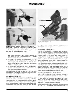
5. Orient the equatorial mount as it appears in Figure 2, at a

latitude of about 40°, i.e., so the pointer next to the latitude
scale is pointing to the hash mark at “40.” To do this, loosen
the latitude lock t-bolt, and turn the latitude adjustment t-
bolt until the pointer and the “40” line up. Then retighten the
latitude lock t-bolt. The declination (Dec.) and right ascen-
sion (R.A.) axes may need re-positioning (rotation) as well.
Be sure to loosen the R.A. and Dec. lock knobs before
doing this. Retighten the R.A. and Dec. lock knobs once
the equatorial mount is properly oriented.

6. Thread the counterweight shaft into the equatorial mount

at the base of the declination axis until tight.

7. Remove the screw and washer on the bottom of the coun-

terweight shaft and slide the counterweight onto the shaft.
Make sure the counterweight lock knob is adequately loos-
ened to allow the counterweight shaft to pass through the
hole. Position the counterweight about halfway up the shaft

and tighten the lock knob. Replace the screw and washer
on the end of the shaft.

8. Remove the two wingnuts from the optical tube assembly.

Place the optical tube assembly on top of the equatorial
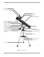
mount and secure it with the wing nuts. Refer to Figure 1
for orientation of the tube.

9. Attach the two slow-motion cables to the R.A. and Dec.

worm gear shafts of the equatorial mount by positioning
the thumbscrew on the end of the cable over the indented
slot on the worm gear shaft and then tightening the thumb-
screw. We recommend that the shorter cable be used on
the R.A. worm gear shaft and the longer cable on the Dec.
worm gear shaft.

10. Remove the two metal thumbnuts located near the focuser

at the front of the optical tube. Place the bracket of the EZ
Finder II on the tube so that the holes in the bracket slide
over the two threaded posts on the tube. The EZ Finder
should be oriented so that it appears as in Figure 1.
Thread the thumbnuts back onto the posts to secure the
EZ Finder II in place.

11. Insert the 25mm Explorer II eyepiece into the focuser

drawtube and secure it in place with the thumbscrew.

Your telescope is now fully assembled and should appear as
it does in Figure 1.

4. Getting Started

Balancing the Telescope

To insure smooth movement of the telescope, it should be prop-
erly balanced. This is done by positioning the counterweight on
its shaft at a point where it is balanced on the R.A. axis.

1. Keeping one hand on the optical tube, loosen the R.A. lock

knob. Make sure the declination lock knob is locked. The

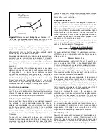
Figure 2. 

The equatorial mount of the SpaceProbe 3 EQ.

4

Declination lock knob
(not shown)

Declination setting circle

R.A. lock knob

Latitude lock T-bolt

R.A. setting circle

Latitude scale

Latitude adjustment T-bolt

Azimuth lock knob

Summary of Contents for SpaceProbe 3 EQ 9844

Page 1: ...Providing Exceptional Consumer Optical Products Since 1975 Customer Support 800 676 1343 E mail support telescope com Corporate Offices 831 763 7000 P O Box 1815 Santa Cruz CA 95061 Orion SpaceProbe 3 EQ 9844 Equatorial Reflector Telescope ...

Page 2: ...b Declination setting circle Counterweight shaft Counterweight Counterweight lock knob Right Ascension lock knob not shown Leg lock knob Eyepiece Focuser Optical tube assembly Right Ascension setting circle Right Ascension slow motion control cable Latitude adjustment T bolt Tripod leg Accessory tray bracket Accessory tray ...

Page 3: ...hould be tightened securely to eliminate flexing and wobbling but be careful not to over tighten or the threads may strip Refer to Figure 1 dur ing the assembly process During assembly and anytime for that matter DO NOT touch the surfaces of the telescope mirrors or the lenses of the finder scope or eyepiece with your fingers The optical sur faces have delicate coatings on them that can easily be ...

Page 4: ...quately loos ened to allow the counterweight shaft to pass through the hole Position the counterweight about halfway up the shaft and tighten the lock knob Replace the screw and washer on the end of the shaft 8 Remove the two wingnuts from the optical tube assembly Place the optical tube assembly on top of the equatorial mount and secure it with the wing nuts Refer to Figure 1 for orientation of t...

Page 5: ... looking through the eyepiece first with your glasses on and then with them off and see if the glasses restrict the view to only a portion of the full field If the glasses do restrict the field of view you may be able to observe with your glasses off by just refocusing the telescope the needed amount If your eyes are astigmatic images will probably appear the best with glasses on This is because a...

Page 6: ...n allowing you to easi ly track the movement of astronomical objects thereby keep ing them from drifting out of the telescope s field of view while you re observing This is accomplished by slowly rotating the telescope on its right ascension R A axis using only the R A slow motion cable But first the R A axis of the mount must be aligned with the Earth s rotational polar axis a process called pola...

Page 7: ... to provide hands free tracking Objects will then remain stationary in the field of view without any manual adjustment of the R A slow motion control cable Understanding the Setting Circles The setting circles on an equatorial mount enable you to locate celestial objects by their celestial coordinates Every object resides in a specific location on the celestial sphere That location is denoted by t...

Page 8: ...as pictured in Figure 1 Again you have to rotate the scope in R A so the counterweight shaft is positioned horizontally Then rotate the scope in Dec so it points to where you want it near the horizon To point the telescope to the east or west or in other direc tions you rotate the telescope on its R A and Dec axes Depending on the altitude of the object you want to observe the counterweight shaft ...

Page 9: ...10mm These give magnifications of 28x and 70x respectively Other eyepieces can be used to achieve higher or lower powers It is quite common for an observer to own five or more eyepieces to access a wide range of magnifications This allows the observer to choose the best eyepiece to use depending on the object being viewed To calculate the magnification or power of a telescope and eyepiece combinat...

Page 10: ...isk of the giant planet and watch the ever changing positions of its four largest moons Io Callisto Europa and Ganymede SATURN The ringed planet is a breathtaking sight when it is well positioned The tilt angle of the rings varies over a period of many years sometimes they are seen edge on while at other times they are broadside and look like giant ears on each side of Saturn s disk A steady atmos...

Page 11: ...etails of how to clean your tele scope s optics 8 Specifications Optical tube Steel Primary mirror diameter 76mm Primary mirror coating Aluminum with silicon dioxide SiO2 overcoat Secondary mirror minor axis 19 9mm Focal length 700mm Focal ratio f 9 2 Focuser Rack and pinion accepts 1 25 eyepieces Eyepieces 25mm and 10mm Explorer II eyepieces 1 25 Magnification 28x with 25mm and 70x with 10mm Moun...

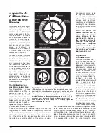
Page 12: ...ourself NOTE The center ring sticker need not ever be removed from the primary mirror Because it lies directly in the shadow of the secondary mirror its presence in no way ad versely affects the optical performance of the tele scope or the image quality That might seem counter intuitive but it s true Aligning the Secondary Mirror With the collimation cap in place look through the hole in the cap a...

Page 13: ...ack end of the optical tube Adjusting the tilt of the mirror requires a push pull technique involving adjustment of each set of collimation screws Loosen the flush screw one full turn and then tighten the adjacent raised screw until it is tight as in Figure 11 do not overtight en Look into the focuser and see if the secondary mirror reflection has moved closer to the center of the primary You can ...

Page 14: ... easily done To clean the secondary mirror it must be removed from the telescope Do this by holding the secondary mirror holder sta tionary with your fingers don t touch the mirror itself while unthreading the Phillips head screw in the center hub of the 3 vaned spider Completely unthread the screw from the holder and the holder will come loose in your fingers Be careful not to lose the spring on ...

Page 15: ...15 ...

Page 16: ...y Watsonville CA 95076 If the product is not registered proof of purchase such as a copy of the original invoice is required This warranty does not apply if in Orion s judgment the instrument has been abused mishan dled or modified nor does it apply to normal wear and tear This warranty gives you specific legal rights and you may also have other rights which vary from state to state For further wa...

Reviews: