


65
VCCX2 Controller Technical Guide
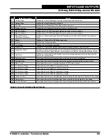
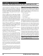
Input/Output Map
See
Table 2, this page
for VCCX2 Controller Inputs/Outputs and
Table 3 for VCC-X EM1 Inputs/Outputs. For the RSM Module
Input/Output tables, please see each individual RSM Module
Technical Guide.
VCCX2 CONTROLLER
Analog Inputs
1
Space Temperature (AI1)
2
Space Slide Adjust (AI2)
3
Supply Air Temperature (AI3)
4
Return Air Temperature (AI4)
5
Building Pressure (AI5)
6
Supply Air Temperature Reset (AI6)
7
Outdoor Air Temperature (AI7)
8
Supply Duct Static Pressure (Duct Static Jack)
Binary Inputs
1
Proof of Flow (BIN1)
2
Dirty Filter (BIN2)
3
Hood On/Off (BIN3)
4
Remote Forced Occupied (BIN4)
5
Remote Forced Cooling (BIN5)
6
Remote Forced Heating (BIN6)
7
Remote Forced Dehumidification (BIN7)
8
Emergency Shutdown (BIN8)
Analog Outputs (0-10 VDC)
1
Main Supply Fan VFD or Bypass Damper (AO1)
2
Economizer (Outdoor Air Damper) or Waterside
Economizer Actuator (AO2)
3
Modulating Heating (Hot Water, Steam, or SCR) (AO3)
4
Exhaust Fan VFD / Building Pressure Control Signal (AO4)
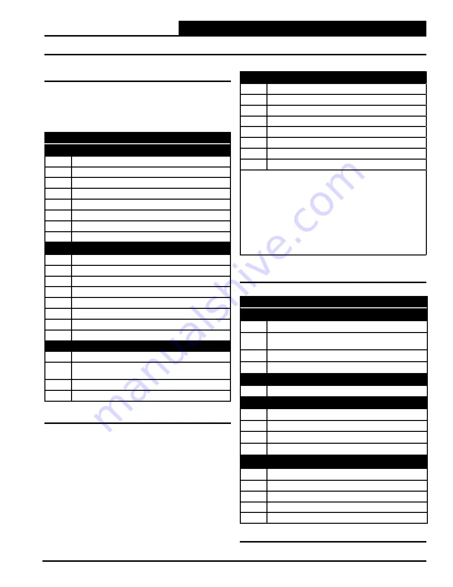
VCC-X EM1 EXPANSION MODULE
Analog Inputs
1
Entering Water Temperature Sensor (T1)
2
Economizer Actuator Feedback (SIG3)
(0-5 or 0-10 V)
3
Return Air Plenum Pressure (SIG1) (0-5V)
4
Exhaust Duct Static Pressure (Duct Static Jack)
Binary Inputs
1
Return/Exhaust Proof of Flow (BIN1)
Analog Outputs (0-10 or 2-10 VDC)
1
Chilled Water (AOUT1)
2
Return Air Damper (AOUT2)
3
Return Air Bypass (AOUT3)
4
Motorized Exhaust Damper (AOUT4)
Relay Outputs (24 VAC)
1
Configurable Relay (R1)
2
Configurable Relay (R2)
3
Configurable Relay (R3)
4
Configurable Relay (R4)
5
Configurable Relay (R5)
Table 2: VCCX2 Controller Inputs and Outputs
Relay Outputs (24 VAC)
1
Fan Relay (RLY1)
2
Configurable Relay (RLY2)
3
Configurable Relay (RLY3)
4
Configurable Relay (RLY4)
5
Configurable Relay (RLY5)
6
Configurable Relay (RLY6)
7
Configurable Relay (RLY7)
8
Configurable Relay (RLY8)
Note:
The following E-BUS sensors and modules are available to
connect to the VCCX2 Controller via E-BUS ports or E-BUS Expansion
Modules:
1.
E-BUS Digital Room Sensor - LCD Display - Temp Only
or Temp and Humidity
2.
E-BUS Digital Room Sensor - No LCD Display - Temp
and Humidity
3. E-BUS Space and Return Air CO
2
Sensors
4.
E-BUS connection to EBTRON, GreenTrol™ and Paragon
airflow stations
5. E-BUS Outdoor Air Temperature and Humidity Sensor
Table 2: VCCX2 Controller Inputs and Outputs
(continued)
Table 3: VCC-X EM1 Inputs and Outputs
INPUTS AND OUTPUTS
VCCX2 Controller and EM1 Module Input/Output Maps


