


25
VCCX2 Controller Technical Guide
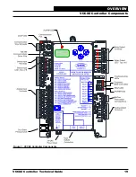
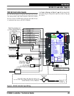
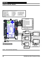
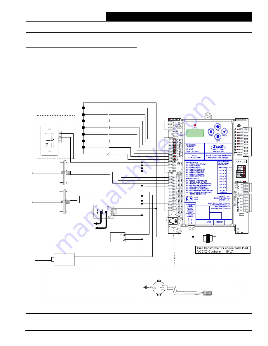
VCCX2 Controller Inputs
The VCCX2 Controller is designed with eight analog inputs,
four analog outputs, eight binary inputs and eight relay outputs.
There are also two E-BUS Expansion Ports which allow the use
of communicating sensors and E-BUS Modules.
See
Figure 6, this page
and
Figure 7, page 26
for wiring details.
Detailed wiring for all inputs and outputs are found on the pages
that follow.
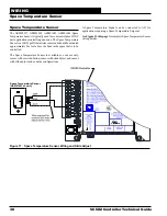
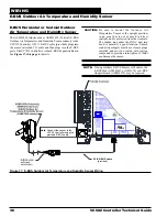
Note:
Either a flush mount room
sensor or a digital E-BUS room
sensor (using a modular E-BUS cable)
may be used.
Proof of Flow Switch
Dirty Filter Switch
Hood ON/OFF
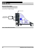
Remote Forced Occupied
Remote Forced Cooling
Remote Forced Heating
Remote Forced Dehumidification
Emergency Shutdown Switch
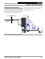
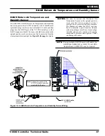
Supply Air Temp. Sensor
Mount in HVAC unit
supply air stream
Space
Temperature Sensor
GND
AUX
TEMP
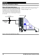
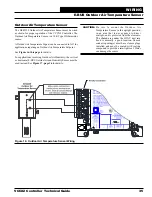
Return Air Temp. Sensor
Mount in HVAC unit
return air stream
Outdoor Air
Temperature Sensor
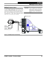
Building Static
Pressure Sensor
Plastic tubing to
building pressure
sensing locations
Remote Supply Air
Temperature Reset Signal
(configurable 0-10VDC) (by others)
EXC
OUT
COM
Connect FRP Tubing to High Pressure Port (bottom tube)
and route to Static Pressure Pickup Probe located in unit discharge.
Leave port marked “LO” open to atmosphere.
Static Pressure
Transducer
Plug into VCCX2
Controller’s
Duct Static Port
18-30 VAC
GND
Line
Figure 6: VCCX2 Controller Input Wiring
WIRING
VCCX2 Controller Inputs


