


64
VCCX2 Controller Technical Guide
Before Applying Power
In order to have a trouble free start-up, it is important to follow a
few simple procedures. Before applying power for the first time,
it is very important to run through a few simple checks.
Power Wiring
One of the most important checks to make before powering up
the system for the first time is to confirm proper voltage and
transformer sizing for each controller. Each VCCX2 Controller
requires 15 VA of power delivered to it at 24 VAC. You may
use separate transformers for each device (preferred) or power
several devices from a common transformer.
WARNING:
Observe Polarity! All boards must be wired
with GND-to-GND and 24 VAC-to-24
VAC. Failure to observe polarity will result
in damage to one or more of the boards.
Check all wiring leads at the terminal block for tightness. Be sure
that wire strands do not stick out and touch adjacent terminals.
Confirm that all sensors required for your system are mounted
in the appropriate location and wired into the correct terminals
on the VCCX2 Controller.
After all the above wiring checks are complete, apply power to
the VCCX2 Controller.
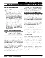
Configuring the Controller
The next step is configuring the controller for your specific
requirements. In order to configure the VCCX2 Controller, you
must use an operator interface. Four different operator interfaces
are available for programming and monitoring of the VCCX2
Controller. See
Figure 45, this page
. They are as follows:
• Modular Service Tool SD
• Modular System Manager SD
•
PC with Prism 2 Software installed and CommLink 5
•
System Manager TS-L (Touch Screen - Limited Access)
Any of these devices or a combination of them can be used to
access the status, configuration, and setpoints of any controller
on your communications loop.
If using the Modular Service Tool SD or the Modular System
Manager SD for programming, refer to the
VCCX2 Controller
Operator Interface SD Technical Guide
. If using a computer
and the Prism 2 software for programming, refer to the
Prism 2
Technical Guide
.
If using the System Manager TS-L for monitoring, please see
the
System Manager TS-L Technical Guide.
No matter which operator interface you use, we recommend that
you proceed with the programming and setup of the VCCX2
Controller in the order that follows:
1. Configure the controller for your application.
2. Program the controller setpoints.
3. Program the controller operation schedules.
4. Set the controller current time and date.
5.
Review the controller status screens to verify system
operation and correct controller configuration.
NOTE:
For BACnet
®
Configuration, see
Appendix C,
page 116
.
STATUS
SETPOINTS
SCHEDULES
OVERRIDES
ALARMS
7
8
0
DEC
MINUS
9
4
5
6
1
2
3
ENTER
ESC
CLLAR
DOWN
UP
PREV
NEXT
Figure 45: Modular Service Tool SD, Modular
System Manager SD, System Manager TS-L,
and Prism 2 Software Operator Interfaces
START-UP AND COMMISSIONING
Powering Up and Configuration


