


51
VCCX2 Controller Technical Guide
Refrigerant System Module for VFD
Compressors
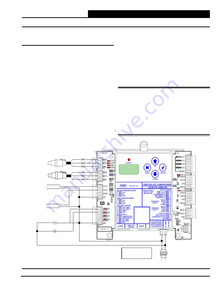
The ASM01686 Refrigerant System Module for VFD Compressors
(RSMV) monitors and controls one tandem refrigeration circuit of
the HVAC unit. The module is designed for R410-A refrigerant.
The RSMV is connected to the VCCX2 Controller. Up to four
RSMV’s can be connected, depending on the size of the system.
There are two E-BUS Expansion Ports which allow the use of
communicating sensors and E-BUS modules.
The RSMV provides four analog inputs, three binary inputs,
three relays, and four analog outputs. See
Figure 32, this page
for inputs wiring and
Figure 33, page 52
for outputs wiring.
The RSMV provides the following:
• Modulates the compressors to satisfy the Suction Coil
(Saturated) Temperature. The Suction Coil (Saturated)
Temperature Setpoint is reset by the VCCX2 Controller
to maintain the Supply Air Temperature during
Cooling Mode. During Dehumidification Mode, it
controls the compressors to the Suction (Saturation)
Temperature Setpoint.
•
Modulates the Condenser Fan to maintain the Head
Pressure Setpoint.
•
Modulates the Expansion Valves to maintain the
Superheat Setpoint.
• Provides alarms and safeties for the compressor and
condenser operation.
•
Provides a 2 x 8 LCD character display and four
buttons that allow for status of system operation, system
setpoints, system configurations, sensors, and alarms,
and to change the module’s address, if necessary.
WARNING:
Observe Polarity! All boards must be
wired with GND-to-GND and 24 VAC-
to-24 VAC. Failure to observe polarity
will result in damage to one or more of the
boards. Expansion modules must be wired
in such a way that the expansion modules
and the controller are always powered
together. Loss of power to the expansion
module will cause the controller to become
inoperative until power is restored to the
expansion module.
Figure 32: RSMV Inputs Wiring
BK
RD
WH
BK
RD
WH
S
P
S
UCTION
RESSURE
ENSOR
H
P
S
EAD
RESSURE
ENSOR
COIL (SUCTION LINE)
TEMP. 2 SENSOR
COMPRESSOR STATUS 1
COMPRESSOR STATUS 2
18-30 VAC
GND
Line Voltage
Size transformer for
correct total load.
RSMV = 18 VA
COIL (SUCTION LINE)
TEMP. 1 SENSOR
WIRING
RSMV Inputs


